22 23
5.6 DeaD BanD setting
MINIGAM+ control board dead band should be adjusted only if the actuator is “hunting”.
In this case, use a small screwdriver to adjust the «Dead Band» potentiometer value until
the actuator stops and stays at the desired position.
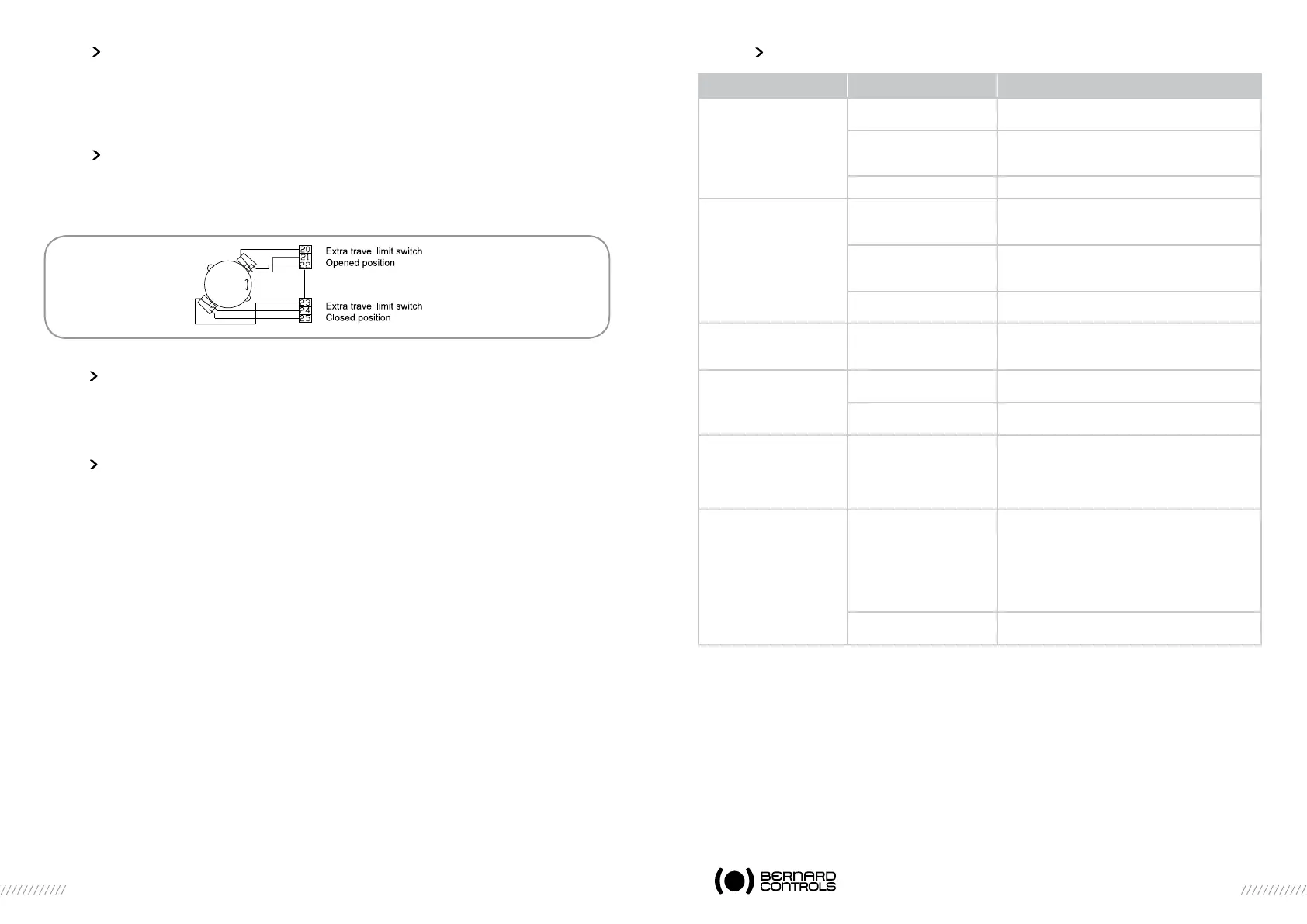
5.7 auXiLiairY controL switches
The OPEN and CLOSED signalling can be managed separately by two separated control switches.
These switches are actuated by brown and grey cams.
They can be connected through terminals 20 to 25as follow :: :
5.8 heating resistor
To avoid any condensation, each EZ actuator is equipped with heating resistor. It’s recommanded to
supply the heater as soon as the actuator is on site.
5.9 caution
Replace covers immediately after start-up and make sure that their seals are clean. Never fail
to replace the protection covers. If water ever enters, dry thoroughly before replacing covers.
5.10 trouBLeshooting
PROBLEM CAUSE CORRECTIVE ACTION
No operation
No LED on.
Motor thermal protective
device tripped
Check if the motor is hot. The actuator will be
available after the motor has cooled down.
Actuator power supply Check the power supply voltage between termi-
nals L and N. Compare to voltage indicated on the
identification plate.
Blown fuse Check the fuse and replace if required..
The actuator does not
follow the commands.
The yellow LED is on :
Torque limit switch is
tripped
f the actuator has stopped on a mechanical stop,
disengage it with the handwheel and set again
the stroke (stops and end of travel switches).
Incorrect switches
configuration
Check the switches are set according to the
actuator configuration (Minigam board)
Check the input signal switches configuration.
Bad wiring Check input signal connection between the
terminals 70 and 71
The actuator does not
stop on the right position
and is hunting.
Dead band setting is not
correct.
See paragraph 5.6
The remote position
feedback signal is wrong.
Bad wiring Check signal with a voltmeter or a milliammeter
between terminals 71 and 72
Incorrect switches
configuration
Check that switches are set correctly
The torque limiter
indication does not
diisappear once the torque
limiter sensor is no longer
tripped.
Torque limiter data storage The torque limiter data are stored electronically.
To clear a torque limiter memory, a reverse
command must be sent.
The actuator does not
follow the input signal.
Reversed potentiomèter Check potentiometer connections.
Potentiometer is connected on 16-17-18 positions :
- 4mA (or 0mA or 0V) = Closed position and
clockwise closing.
Potentiometer on 18-17-16 positions :
- 4mA (or 0mA or 0V) = Open position and
clockwise closing.
Direction of rotation Check switch 7 setting :
Switch 7 on A : clockwise rotation for closing.
 Loading...