EFL Operator Guide
Installation
Part No. MAN/EN5103-0076 Page 11 of 34 Revision A (Jan 2014)
Installation
This section describes mounting and alignment concerns for the EFL system. To
obtain accurate results, the LaserSpeed gauges must be orientated properly with
respect to the fiber optic cable and buffer tube. The orientation consists of placing the
fiber optic cable or buffer tube in the proper position so measurements can be made.
Once the fiber optic or buffer tube is properly located in the measuring volume of the
laser beam crossing, angular alignment must be optimized to make accurate readings.
The location of the cable with respect to the LaserSpeed gauges is illustrated in the
figure below.
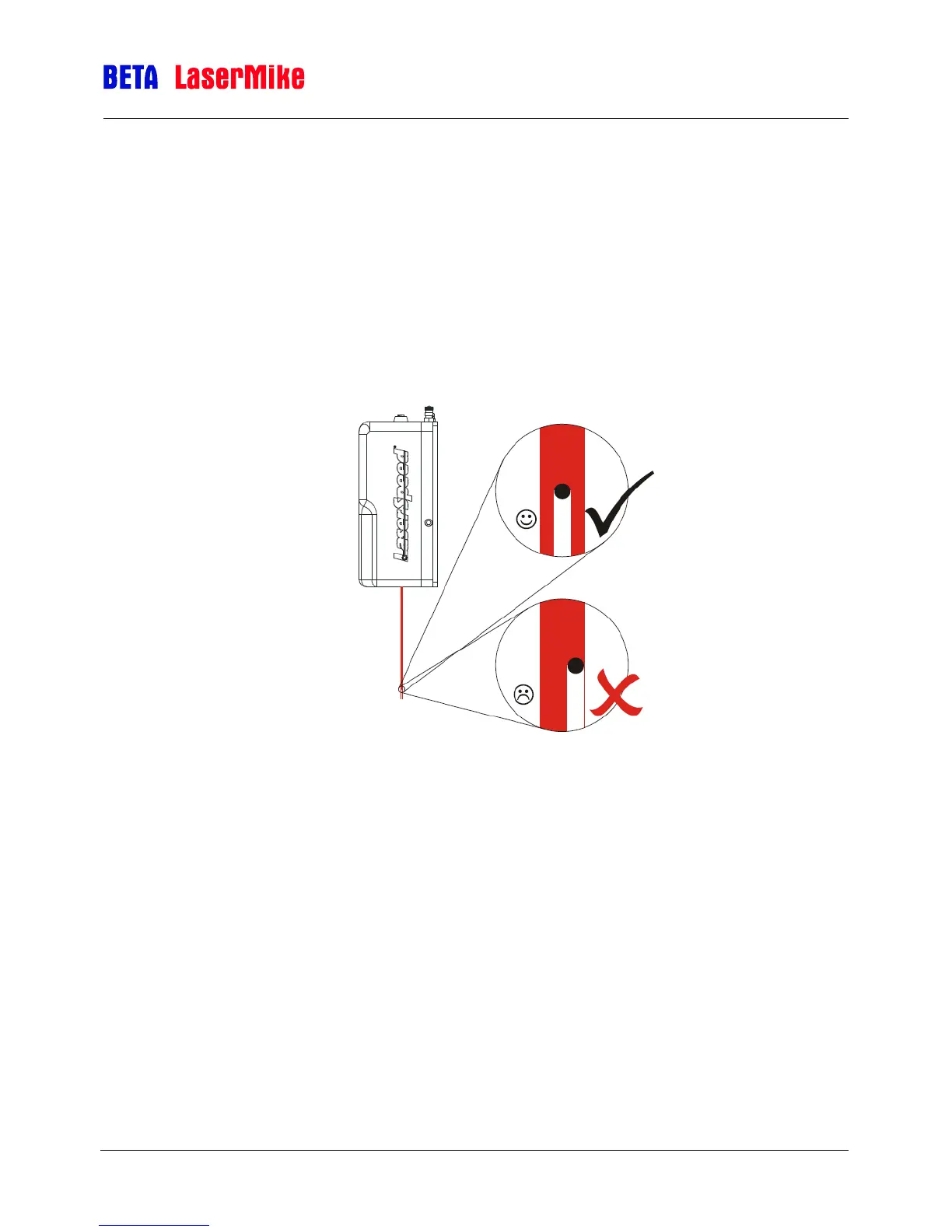
Gauge alignment for optical fiber
Positional Mounting
Positional mounting places the fiber optic cable or buffer tube in the area where the
laser beams cross. Within this region, the instrument will make measurements. The
LaserSpeed gauges have optional guides for both the fiber optic cable and the buffer
tube. These guides should provide the proper positional alignment for the fiber or
buffer tube. The guides can help to position the fiber and cable in the measurement
region of the LaserSpeed gauge. The optical fiber should be positioned in the center of
the laser beam as shown in the figure above. The Laser beam should hit the center of
the buffer tube or cable +/- 10% of the cable diameter.