ITALIANO
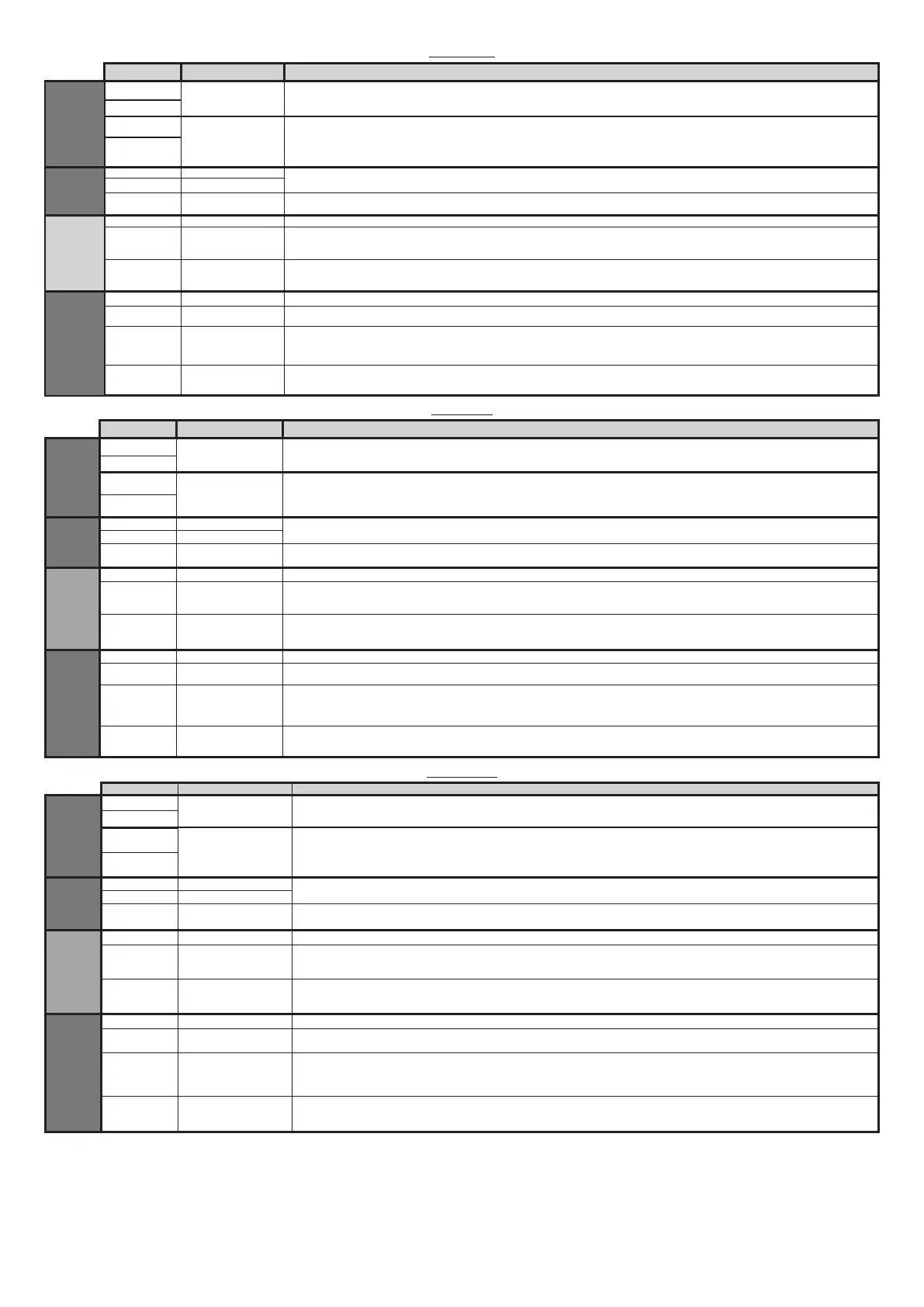
Morsetto Denizione Descrizione
Aux
20
AUX 0 - CONTATTO
ALIMENTATO 24V
(N.O.) (1A MAX)
Uscita per LAMPEGGIANTE.
Il contatto rimane chiuso durante la movimentazione delle ante.
21
26
AUX 3 - CONTATTO
LIBERO (N.O.)
(Max 24V 1A)
Uscita congurabile AUX 3 - Default Uscita 2°CANALE RADIO.
CANALE RADIO MONOSTABILE / SPIA CANCELLO APERTO SCA / COMANDO LUCE CORTESIA / MANUTENZIONE / STATO CANCELLO CHIUSO /
CANALE RADIO BISTABILE / CANALE RADIO TEMPORIZZATO / STATO CANCELLO APERTO / USCITA 1 PROGRAMMABILE IN ALTEZZA / USCITA
2 PROGRAMMABILE IN ALTEZZA
27
Alim.
Accessori
50 24V-
Uscita alimentazione accessori.
51 24V+
52 24 Vsafe+
Uscita alimentazione per dispositivi di sicurezza vericati (trasmettitore fotocellule).
Uscita attiva solo durante il ciclo di manovra.
Comandi
60 Comune Comune ingressi IC 1 e IC 2
61 IC 1
Ingresso di comando congurabile 1 (N.O.) - Default START E.
START E / START I / OPEN / CLOSE / PED / TIMER / TIMER PED
Far riferimento alla tabella “Congurazione degli ingressi di comando”.
62 IC 2
Ingresso di comando congurabile 2 (N.O.) - Default PED.
START E / START I / OPEN / CLOSE / PED / TIMER / TIMER PED
Far riferimento alla tabella “Congurazione degli ingressi di comando”.
Sicurezze
70 Comune Comune ingressi STOP, SAFE 1 e SAFE 2
71 STOP
Il comando interrompe la manovra. (N.C.)
Se non si utilizza lasciare il ponticello inserito.
72 SAFE 1
Ingresso di sicurezza congurabile 1 (N.C.) - Default BAR.
PHOT / PHOT TEST / PHOT OP / PHOT OP TEST / PHOT CL / PHOT CL TEST / BAR / BAR TEST / BAR 8K2 /
BAR OP / BAR OP TEST / BAR
8K2 OP/ BAR CL / BAR CL TEST / BAR 8K2 CL /STOP 8K2
Far riferimento alla tabella “Congurazione degli ingressi di sicurezza”.
73 SAFE 2
Ingresso di sicurezza congurabile 2 (N.C.) - Default PHOT.
PHOT / PHOT TEST / PHOT OP / PHOT OP TEST / PHOT CL / PHOT CL TEST / BAR / BAR TEST / BAR OP / BAR OP TEST / BAR CL / BAR CL TEST
Far riferimento alla tabella “Congurazione degli ingressi di sicurezza”.
ENGLISH
Terminal Denition Description
Aux
20
AUX 0 - 24V POWERED
CONTACT (N.O.)
(MAX. 1A)
FLASHING LIGHT output .
The contact remains closed during the movement of the leaves.
21
26
AUX 3 - FREE
CONTACT (N.O.)
(MAX. 24V 1A)
AUX 3 congurable output - Default setting MONOSTABLE RADIO CHANNEL
MONOSTABLE RADIO CHANNEL / SCA OPEN GATE INDICATOR LIGHT / COURTESY LIGHT CONTROL / MAINTENANCE / CLOSED GATE STATE /
BISTABLE RADIO CHANNEL / TIMED RADIO CHANNEL / OPEN GATE STATE / HEIGHT PROGRAMMABLE OUTPUT 1 / HEIGHT PROGRAMMABLE
OUTPUT 2
27
Accessories
power
supply
50 24V-
Accessories power supply output.
51 24V+
52 24 Vsafe+
Tested safety device power supply output (photocell transmitter).
Output active only during operating cycle.
Commands
60 Common IC 1 and IC 2 inputs common
61 IC 1
Congurable command input 1 (N.O.) - Default START E.
START E / START I / OPEN / CLOSE / PED / TIMER / TIMER PED
Refer to the “Command input conguration” table.
62 IC 2
Congurable command input 2 (N.O.) - Default PED.
START E / START I / OPEN / CLOSE / PED / TIMER / TIMER PED
Refer to the “Command input conguration” table.
Safety devices
70 Common STOP, SAFE 1 and SAFE 2 inputs common
71 STOP
The command stops movement. (N.C.)
If not used, leave jumper inserted.
72 SAFE 1
Congurable safety input 1 (N.C.) - Default BAR.
PHOT / PHOT TEST / PHOT OP / PHOT OP TEST / PHOT CL / PHOT CL TEST / BAR / BAR TEST / BAR 8K2 /
BAR OP / BAR OP TEST / BAR
8K2 OP/ BAR CL / BAR CL TEST / BAR 8K2 CL /STOP 8K2
Refer to the “Safety input conguration” table.
73 SAFE 2
Congurable safety input 2 (N.C.) - Default PHOT.
PHOT / PHOT TEST / PHOT OP / PHOT OP TEST / PHOT CL / PHOT CL TEST / BAR / BAR TEST / BAR OP / BAR OP TEST / BAR CL / BAR CL TEST
Refer to the “Safety input conguration” table.
FRANÇAIS
Borne Dénition Description
Aux
20
AUX 0 - CONTACT
ALIMENTÉ 24V (N.O.)
(1 A MAX)
Sortie pour CLIGNOTANT.
Le contact reste fermé pendant le mouvement des vantaux.
21
26
AUX 3 - CONTACT
LIBRE (N.O.)
(Max 24V 1A)
Sortie congurable AUX3 – Défaut Sortie 2ème CANAL RADIO.
CANAL RADIO MONOSTABLE/VOYANT DE PORTAIL OUVERT SCA/COMMANDE DE LUMIÈRE DE COURTOISIE/ENTRETIEN/ÉTAT DE PORTAIL
FERMÉ/CANAL RADIO BISTABLE/CANAL RADIO TEMPORISÉ/ÉTAT DE PORTAIL OUVERT/SORTIE 1 PROGRAMMABLE EN HAUTEUR/SORTIE 2
PROGRAMMABLE EN HAUTEUR
27
Alimentation
des
accessoires
50 24V-
Sortie alimentation accessoires.
51 24V+
52 24 Vsafe+
Sortie alimentation des dispositifs de sécurité vériés (émetteur photocellules)
Sortie active uniquement pendant le cycle de manœuvre.
Commandes
60 Commun Commun entrées IC 1 et IC 2
61 IC 1
Entrée de commande congurable 1 (N.O.) - Défaut START E.
START E / START I / OPEN / CLOSE / PED / TIMER / TIMER PED
Consulter le tableau “Conguration des entrées de commande”.
62 IC 2
Entrée de commande congurable 2 (N.O.) - Défaut PED.
START E / START I / OPEN / CLOSE / PED / TIMER / TIMER PED
Consulter le tableau “Conguration des entrées de commande”.
Sécurités
70 Commun Commun entrées STOP, SAFE 1 et SAFE 2
71 STOP
La commande interrompt la manœuvre. (N.F.)
Si vous ne l’utilisez pas, laissez la barrette en place.
72 SAFE 1
Entrée de sécurité congurable 1 (N.F.) - Défaut BAR.
PHOT / PHOT TEST / PHOT OP / PHOT OP TEST / PHOT CL / PHOT CL TEST / BAR / BAR TEST / BAR 8K2 /
BAR OP / BAR OP TEST / BAR
8K2 OP/ BAR CL / BAR CL TEST / BAR 8K2 CL /STOP 8K2
Consulter le tableau “Conguration des entrées de sécurité”.
73 SAFE 2
Entrée de sécurité congurable 2 (N.C.) - Défaut PHOT.
PHOT / PHOT TEST / PHOT OP / PHOT OP TEST / PHOT CL / PHOT CL TEST / BAR / BAR TEST / BAR OP / BAR OP TEST / BAR CL / BAR CL TEST
Consulter le tableau “Conguration des entrées de sécurité”.
10-ARGO BT A 20-35
D814038 0AA00_03
 Loading...