INSTALLATION COMFORT CIRCLE
26
2.15.2 Input in controller
The controller has one input signal interface, to which a timer
is usually connected.
The signal switches the unit on or off. Depending on the set-
ting 1 in the timer menu, the unit either can or cannot be
switched on or off using the
=-key (see section 5).
The operation is global – the signal affects all units connected
to the controller.
Caution:
c The input is designed for controls with potential-free con-
tacts, and is not to be loaded.
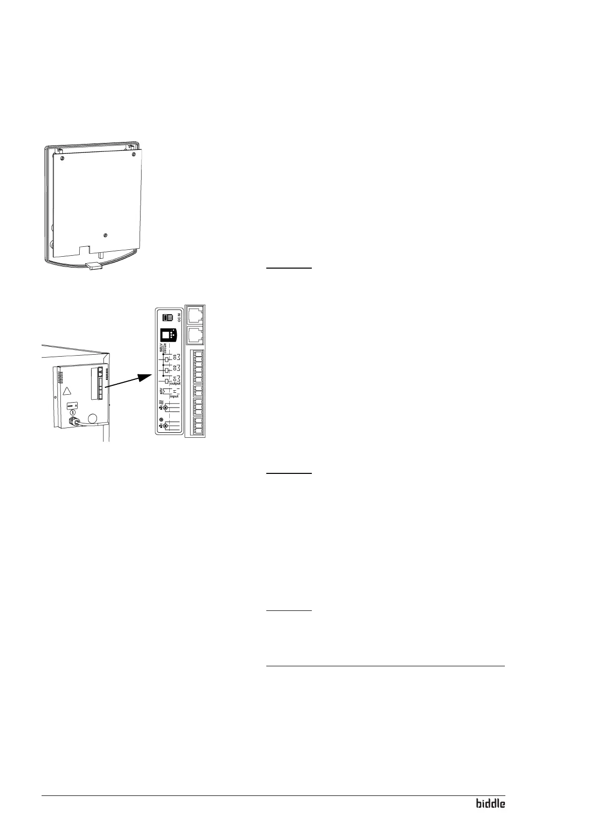
2.15.3 Input in unit
The unit has one input signal interface 1, to which a timer, a
low-limit or room thermostat or a BMS signal may be con
-
nected.
The effect of the input signal depends on the controller set-
tings. (see section 4.2.3). A signal to one unit will have the
same effect on all units linked with that unit.
Caution:
c The input is designed for controls with potential-free con-
tacts, and is not to be loaded.
2.15.4 Outputs in unit
The unit has interfaces 2 for three output signals: these can
be used for, for instance, controlling the central-heating or
cooling system, or for transmitting status reports to a BMS.
Caution:
c The outputs are potential-free contacts (relays). Their
maximum load is 24V and 1A.
Danger:
d Connect SELV circuits only – Safety Extra Low
Voltage circuits.
The function of the outputs depends on the controller setting
(see section
4.3.3).
1
1
2
 Loading...