MANUAL INSTALLATION
Version: 1.0 (22-09-2005) 27
The operation is global, being identical for all units connected
to the controller. If a signal activates one unit, all linked units
will also be activated.
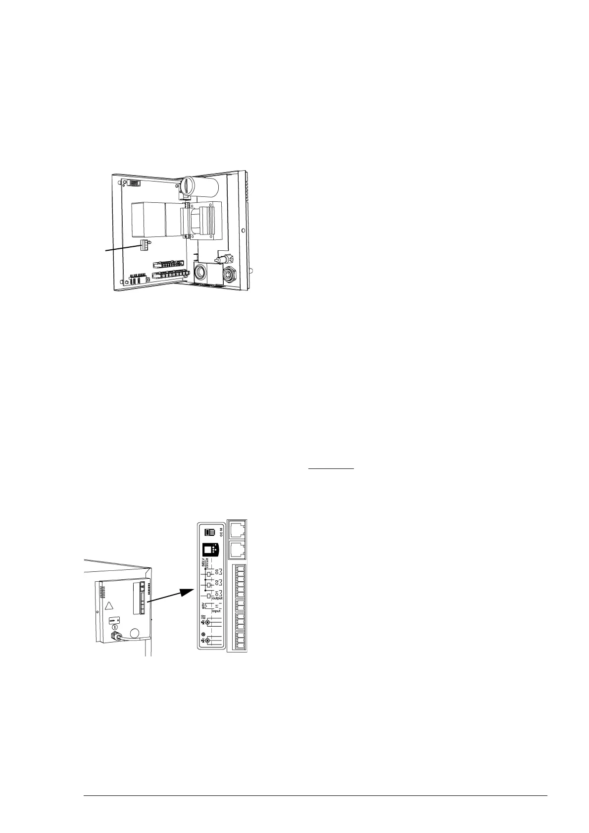
2.15.5 0-10VDC in- and output (CC M)
The 0-10VDC in- and output 1 are located on the PCB 2 in
the unit. To access these, the electronics module must be
removed from the unit (see section
8.6.3).
The 0-10VDC input can, for instance, be used to let a CO
2
sensor determine the ventilation setting.
The 0-10VDC output can, for instance, be used for control-
ling an extraction fan.
2.15.6 Options and operation
Options and operation depend on the in- or output as well as
on the controller settings. These are further described in sec
-
tion 4.5.
2.15.7 Connecting in- and outputs
The connections are located on the unit’s connector plate.
The corresponding connectors are located in the terminals.
Caution:
c For all connections, allow for approx. 30 cm extra cable
length – it will be needed to easily take the electronics out
when servicing the unit.
Connecting in- and outputs
• Connect the output signal cable to terminal 1.
• Connect the input signal cable to terminal 2.
1
2
1
2
 Loading...