24
MAN 604A Rev. 5
Operation and Use
Section 3: Operation and Use
3.4 Preparation for Start-up
3.4.1 Pneumatic Connections
Connect the actuator to the pneumatic feed line with ttings and pipes in accordance to
the plant specications. They must be sized correctly in order to guarantee the necessary
airow for the operation of the actuator, with pressure drops not exceeding the maximum
allowable value. The shape of the connecting piping must not cause excessive stress to the
inlets of the actuator. The piping must be suitably fastened so as not to cause excessive
stress or loosening of threaded connections, if the system undergoes strong vibrations.
Every precaution must be taken to ensure that any solid or liquid contaminants, which
may be present in the pneumatic pipe work to the actuator, are removed to avoid possible
damages to the unit or loss of performance.
The inside of the pipes used for the connections must be well cleaned before use: wash
them with suitable substances and blow through them with air or nitrogen. The ends of the
tubes must be well debarred and cleaned.
Once the connections are completed, operate the actuator and check that it functions
correctly, that the operation times meet the plant requirements and that there are no leaks
in the pneumatic connections.
NOTICE
If necessary to mount components not in Bif scope of supply, please check the accessories
mounting hole details in the documents TN 1028 (for metric dimension) or TN 1028U
(for imperial dimension).
June 2020
Installation, Operation and Maintenance Manual
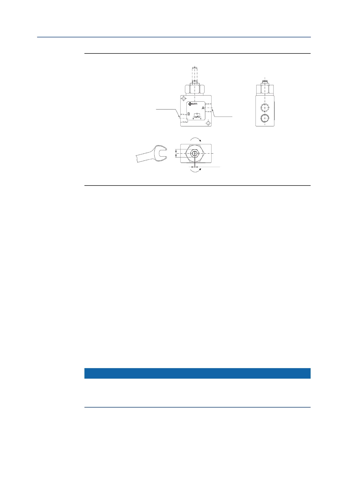
Figure 19 Adjustment of operating time
Pneumatic
connection
Pneumatic
connection
(Close) screw for decrease speed
(open) unscrew for increase speed of operation
Item 278:
see operating diagram
Screwdriver
Wrench