37
MAN 604A Rev. 5
Layouts and Sectional Drawings
Section 7: Layouts and Sectional Drawings
June 2020
Installation, Operation and Maintenance Manual
Section 7: Layouts and Sectional Drawings
7.1 Parts List for Maintenance and
Replacing Procedure
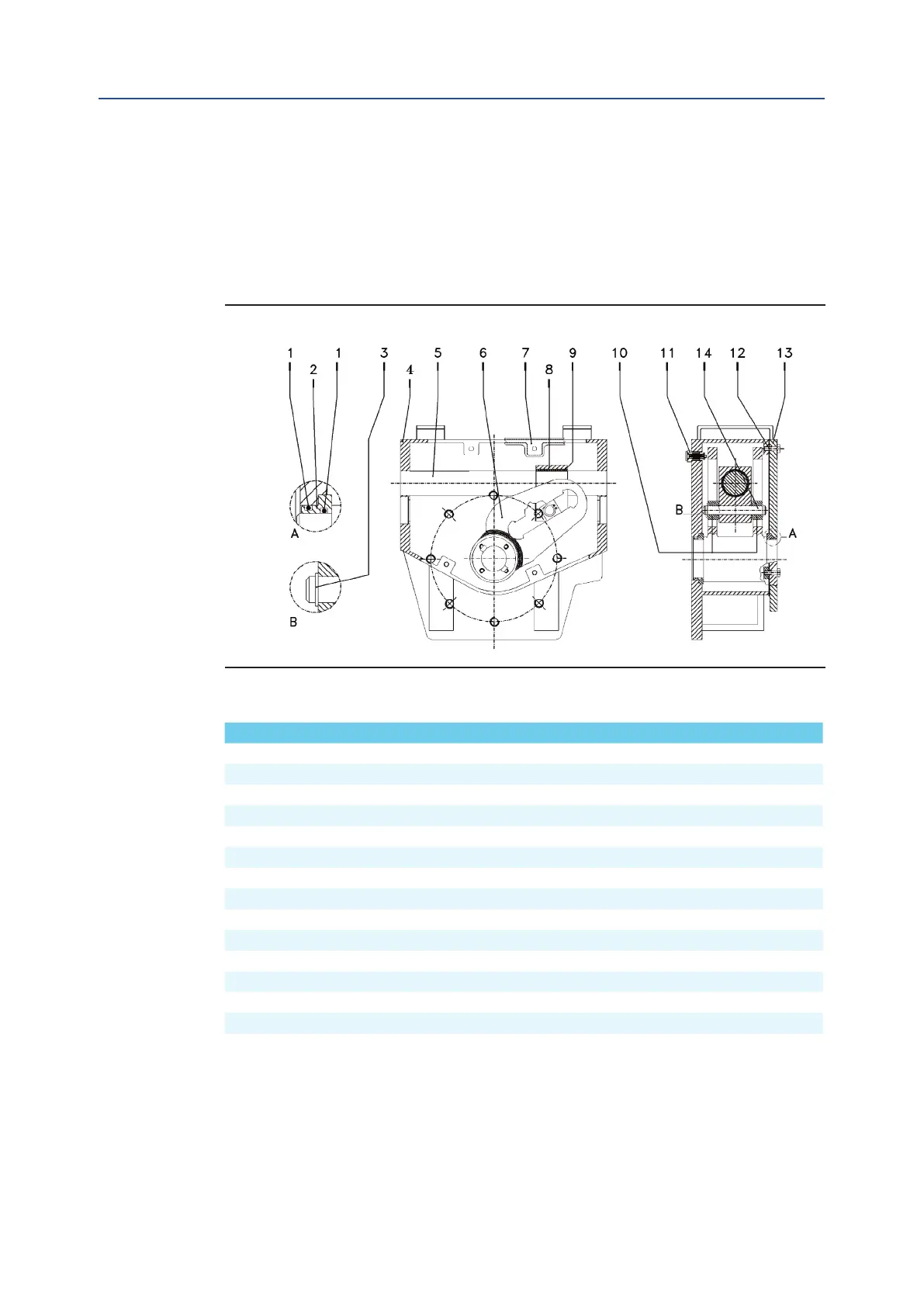
Figure 23 Scotch yoke Mechanism (standard version)
Table 19. Parts list
Item Qty Description Material
1 4 O-ring * NBR rubber
2 2 Yoke bushing Bronze
3 2 Retainer ring Stainless steel
4 1 Housing Carbon steel
5 1 Guide bar Alloy steel
6 1 Yoke Carbon steel
7 1 Cover gasket * SBR+Cellulose+Fillers
8 1 Guide block Carbon steel
9 1 Bushing Steel + bronze + PTFE
10 2 Sliding block Bronze
11 1 Vent valve * Stainless steel
12 12 Screw Carbon steel
13 1 Cover Carbon steel
14 1 Guide block pin Alloy steel
NOTE:
* Recommended spare parts
Cycles performed by actuator in a 25 years expected lifetime - the minimum performed cycles are guarantied
by Bif based on service conditions listed:
— All the valve required torques have to be lower than actuator max operating torque (MOT).
— The ratio between valve required running torque and actuator max operating torque (MOT)
has to be >1.5.
— The actuator mechanism has to be lubricated in accordance witn indication given on this IOM.