38
MAN 604A Rev. 5
Layouts and Sectional Drawings
Section 7: Layouts and Sectional Drawings
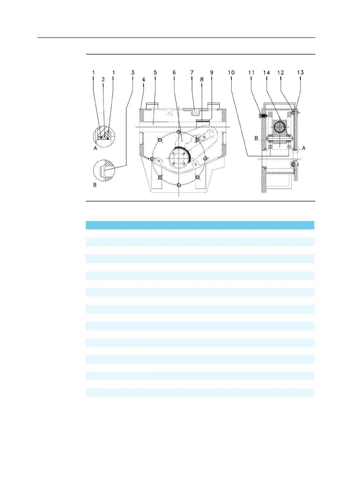
Figure 24 Scotch yoke Mechanism (heavy duty version)
Table 20. Parts list
Item Qty Description Material
1 2 O-ring * NBR rubber
2 2 Yoke bushing Carbon steel
3 2 Washer Stainless steel
4 1 Housing Carbon steel
5 1 Guide bar Alloy steel
6 1 Yoke Carbon steel
7 1 Cover gasket * SBR + Cellulose + llers
8 1 Guide block Carbon steel
9 1 Bushing Steel + Fiberglide
10 2 Sliding block Carbon steel
11 1 Vent valve * Stainless steel + Fluorosiliconic rubber
12 12 Screw Carbon steel
13 1 Cover Carbon steel
14 1 Guide block pin Alloy steel
16 2 Screw Stainless steel
17 2 Yoke supporter washer Ertacetal
18 2 Yoke bushing sit Steel + Fiberglide
19 2 Guide block pin bushing Steel + Fiberglide
20 4 Sliding block sit Steel + Fiberglide
21 2 O-ring * NBR rubber
June 2020
Installation, Operation and Maintenance Manual
NOTE:
* Recommended spare parts
Cycles performed by actuator in a 25 years expected lifetime - the minimum performed cycles are guarantied
by Bif based on service conditions listed:
— All the valve required torques have to be lower than actuator max operating torque (MOT).
— The ratio between valve required running torque and actuator max operating torque (MOT) has to be >1.5.
— The actuator mechanism has to be inspected, lubricated, seals and gaskets have to be replaced after each
200.000 cycles.