5
X
P
K
ØM
Ø
d
1
max
Ø d
4
h
1
Ø d
3
±0.2
H max
45
°
W
0.1 220 102 M10 50 4 7 17 121 22 25 32
MAN 604A Rev. 5
Installation
Section 2: Installation
2.3 Assembling the Actuator onto the Valve
2.3.1 Types of Assembly
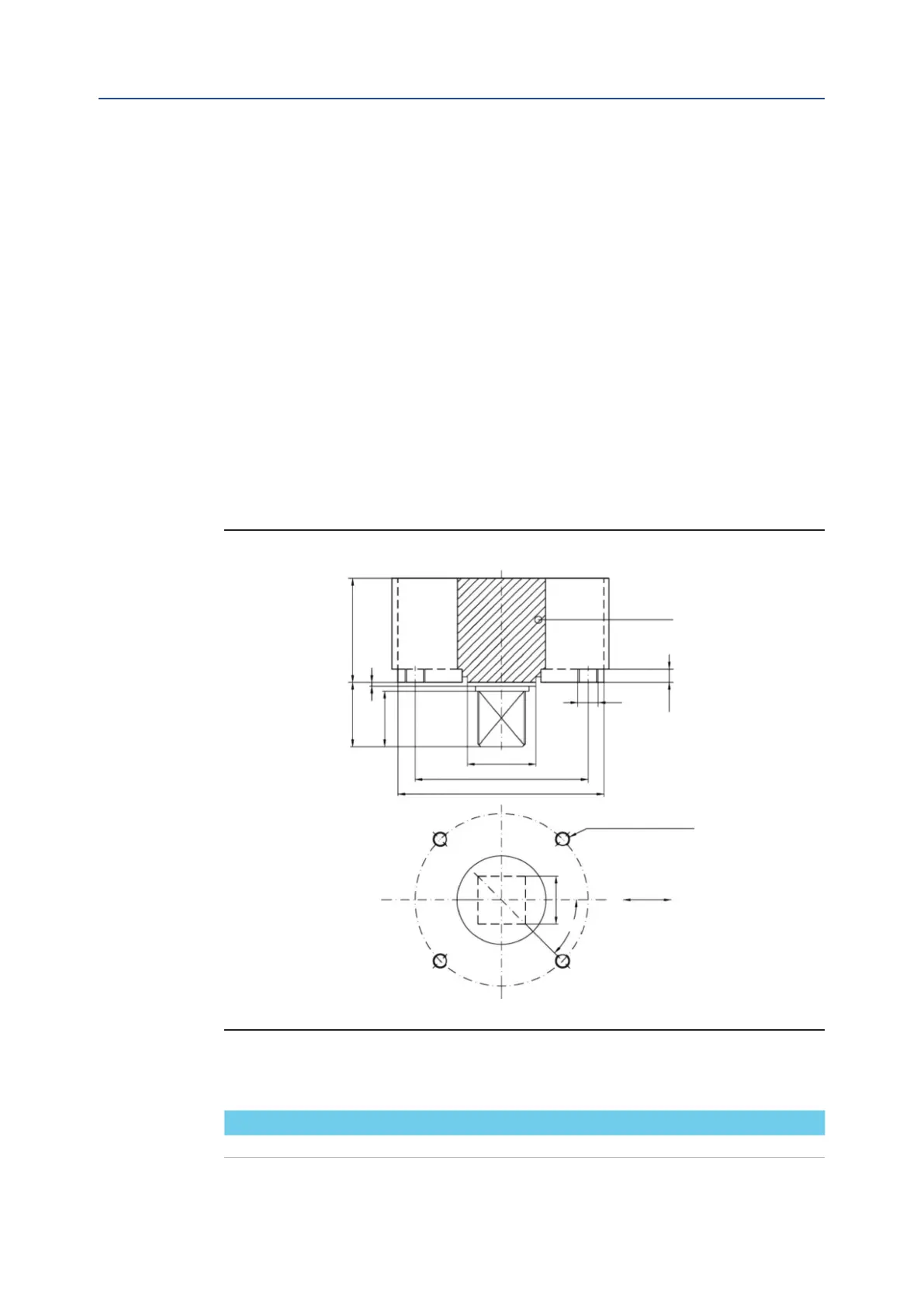
For coupling to the valve, the housing is provided with a ange with threaded holes
according to Bif standard tables (SCN6200; SCN6200-1; SCN6201; SCN6201-1
SCN6201-3 SCN6201-5). The number, dimensions and diameter of the holes are made
in accordance with ISO 5211, but for actuator models 0.3 to 6 the holes are drilled on
the centreline in order to allow an easier assembly of an intermediate ange, when
required. This intermediate ange (or spool-piece) can be supplied when the valve ange
cannot directly match the actuator ange in its “standard” conguration. For the biggest
actuator models, the actuator ange can be machined in accordance with the valve
ange dimensions.
The yoke has bored with keyways for coupling to the valve stem, the dimensions of which
are according to Bif standard tables SCN6200* and SCN6201*.
Figure 2
N. THREADED HOLES
PCD, holes, number and
size according to ISO 5211
Top view of the scotch yoke mechanism
(actuator shown in closed position)
Drive sleeve
Flow line
Dimensions in millimeters
Actuator model Ø d
1
Ø d
3
Ø d
4
ØM N P h
1
H max W K X
Installation, Operation and Maintenance Manual
June 2020
Table 2.