6
Ø d
1
max
Ø d
4
h
2
Ø d
2
+0.1
0
Ø d
5
+0.2
+0.1
K
+0.4
0
Ø d
3
±0.2
h
1
+0.5
0
H max
45
°
W
D10
0.3 240 93 165 M20 4 5 17 127 70 12 75.6
0.9 310 112 254 M16 8 5 19 150 86 14 96.6
1.5 360 144 298 M20 8 6 19 190 112 18 119.0
3 430 195 356 M30 8 9 23 200 157 25 167.8
6 520 250 406 M36 8 14 29 260 200 28 212.8
MAN 604A Rev. 5
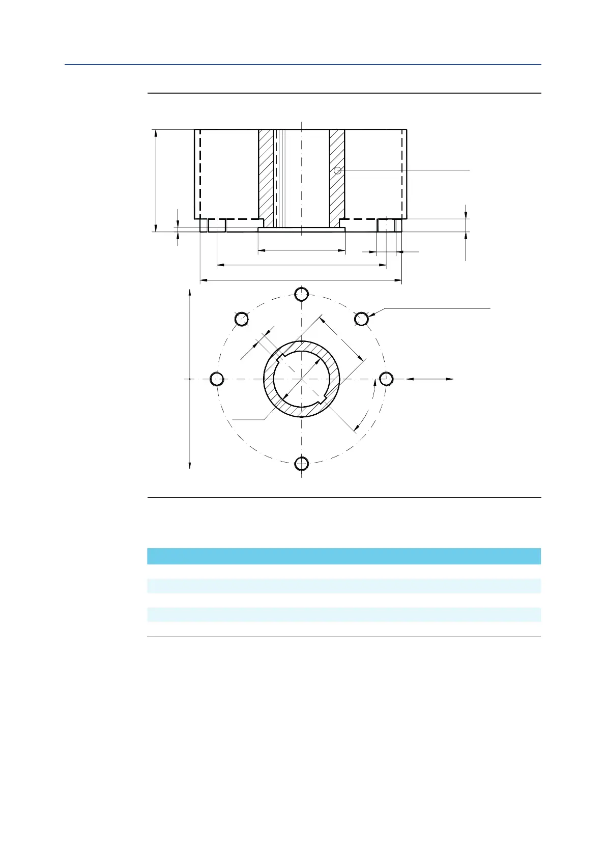
Installation
Section 2: Installation
Dimensions in millimeters
Actuator model Ø d
1
Ø d
2
Ø d
3
Ø d
4
N h
1
h
2
H max Ø d
5
W K
Figure 3
Drive sleeve
N. THREADED HOLES
PCD, holes, number and size
according to ISO 5211
(but the holes are on centerline
instead of straddle the centerline)
Top view of the scotch yoke mechanism
(actuator shown in closed position)
Flow line
N.8 holes angeN.4 holes ange
June 2020
Installation, Operation and Maintenance Manual
Table 3.