7
Ø d
1
max
Ø d
4
h
2
Ø d
2
+0.1
0
Ø d
5
+0.2
+0.1
K
+0.4
0
Ø d
3
±0.2
h
1
+0.5
0
H max
W
D10
14 580 250 483 M36 12 10 29 340 175 45 195.8
MAN 604A Rev. 5
Installation
Section 2: Installation
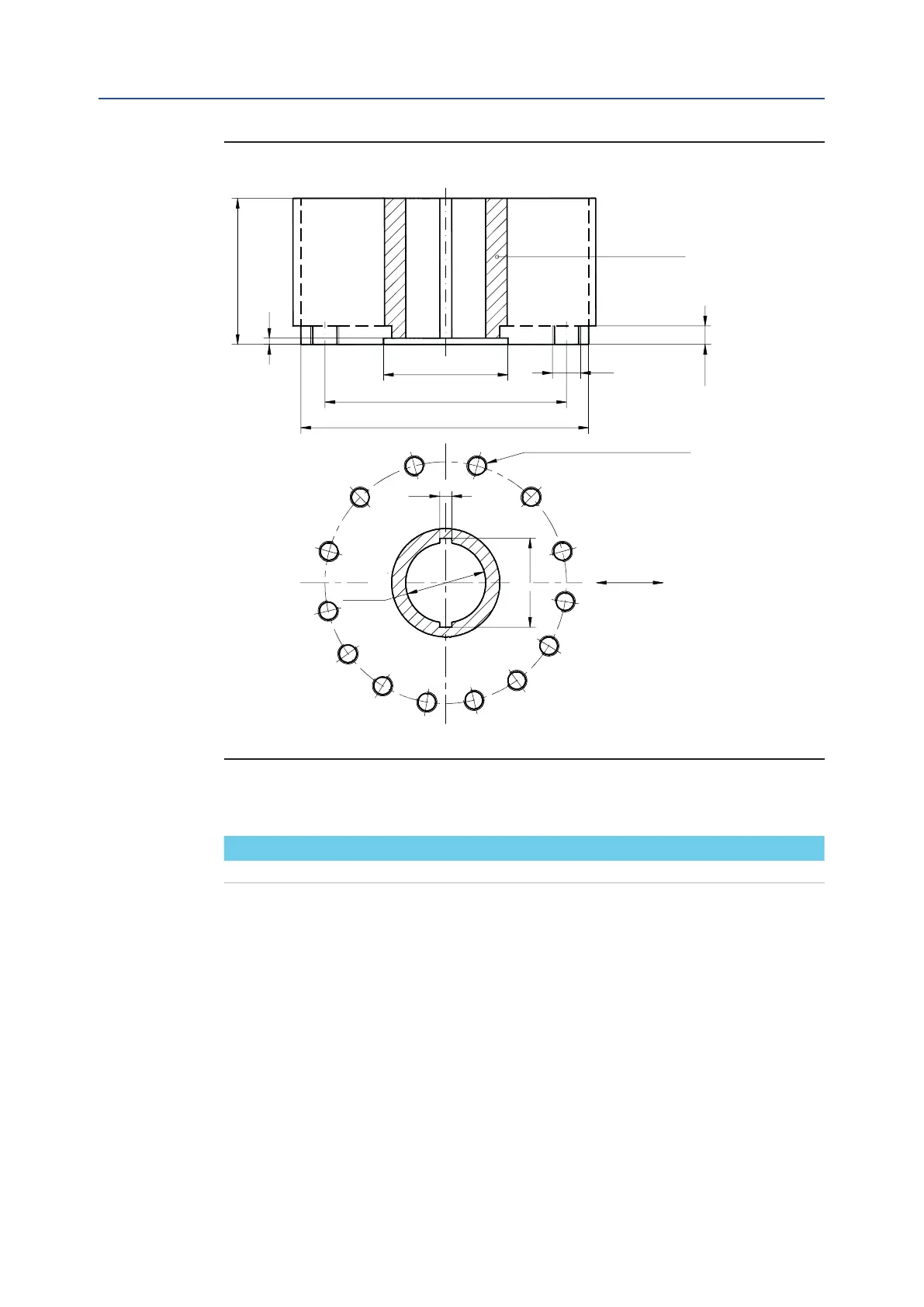
Dimensions in millimeters
Actuator model Ø d
1
Ø d
2
Ø d
3
Ø d
4
N h
1
h
2
H max Ø d
5
W K
Figure 4
Drive sleeve
N. THREADED HOLES
PCD, holes, number and
size according to ISO 5211
Top view of the scotch yoke mechanism
(actuator shown in closed position)
Flow line
Installation, Operation and Maintenance Manual
June 2020
Table 4.