12’–24’ BASIC 6
®
29
WWW.BIGASSFANS.COM ©2012 DELTA T CORP. ALL RIGHTS RESERVED
12’–24’ BASIC 6
®
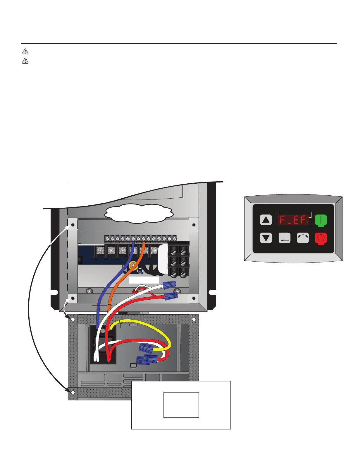
Wiring: ESFR (Early Suppression Fast Response)
WARNING: Wait three minutes after disconnecting before servicing!
WARNING: Improper installation can cause electric shock or damage to the motor and controller. A qualied electrician
should perform the installation.
ATTENTION: If installing the fan in the United States, the fan must be installed per the following National Fire Protection
Association (NFPA) guidelines:
• The fan must be centered approximately between four adjacent sprinklers.
• The vertical distance from the fan to the sprinkler deector must be at least 3 ft (91.4 cm).
• The fan must be interlocked to shut down immediately upon receiving a waterow signal from the alarm system.
The re relay included with the fan is needed only if the fan will be installed in a building that has a re sprinkler system. The re relay
integrates the fan with the sprinkler system and shuts down the fan upon receiving an alarm signal from the system. If the building in
which the fan will be installed has a sprinkler system, you must install the relay according to the instructions below.
A contact closure across the digital input terminals 4 and 13A will result in fan shutdown. The included relay uses a Normally Open
(N.O.) contact as shown below. The relay coil must be energized by the FACP for fan shutdown. Optionally, the normally closed (N.C.)
relay contact can be used. The relay coil must remain energized by the FACP for fan operation. This would be considered a fail safe or
fail open wiring arrangement. Two additional relay coil leads are provided to facilitate supervision pass-through where required.
Electrical Installation (cont.)
U/T1 V/T2 W/T3
PE
L1 L2 L3
1 2 5 6 13A13B13C 14 30 16 1725 4 11
1 2 5 6 13A13B13C 14 30 16 1725 4 11
L1
L2
L3
PAM-SD
M
R F
RUN
STOP
AUTO FWD
REV
Relay is mounted to the
backside of the access cover.
An alarm condition will stop the fan and
issue an “F_EF” external fault on the
controller’s display.
Relay Coil/Contact Details
White (X2) (-) C Blue
NC Yellow
Red (X2) (+) NO Orange
Coil: 20–32 VDC @ 20 mA
Terminals 4 & 13A
for ESFR Relay
From Main FACP or
NAC Box if Applicable
BLU
ORG
REDWHT
YEL