EasyManuals Logo

BIGTREETECH OCTOPUS User Manual

BIGTREETECH OCTOPUS
25 pages
To Next Page IconTo Next Page
To Previous Page IconTo Previous Page
Page #14 background imageLoading...
Page #14 background image
Produced by BIGTREETECH
Page 13 of 25
4 MOTHERBOARD JUMPER SETTINGS
4.1 FAN AND PROXIMITY SWITCH SETTINGS
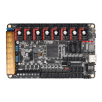
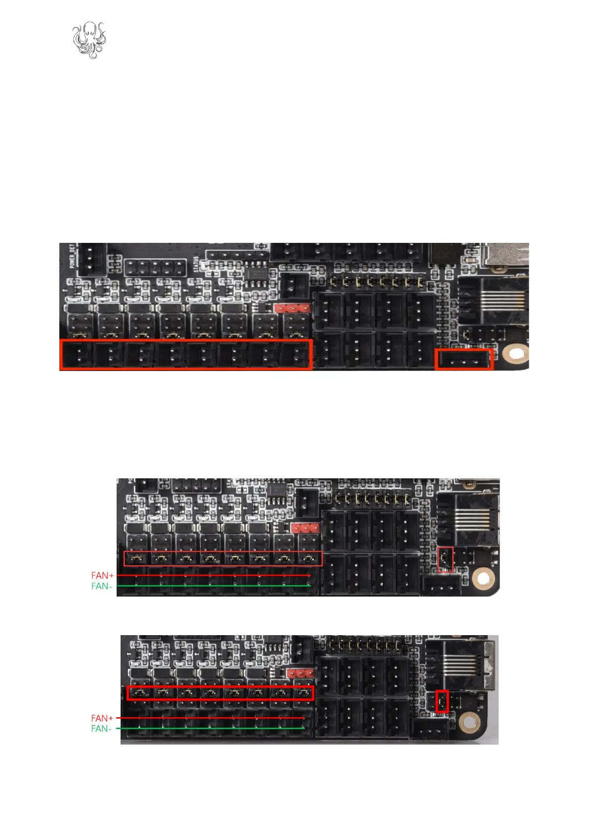
The Octopus features 6 PWM fan outputs and two “always on” fan outputs. There is also a
dedicated pin header for a proximity sensor. These headers are shown in the image below.
Note: The polarity of the fan ports was erroneously swapped on the silkscreen
on the underside of some early boards. To be sure of the correct polarity,
please consult the PINS.pdf document or see the images below.
All of the fan outputs and the proximity sensor input can individually have the voltage
supplied by their pin header selected by configuring the jumpers associated with each
header.
Configure the jumpers as below to select 24V (note that all are shown in the same
configuration even though they can be individually configured).
Configure the jumpers as below to select 12V.

Questions and Answers:

Question and Answer IconNeed help?

Do you have a question about the BIGTREETECH OCTOPUS and is the answer not in the manual?

BIGTREETECH OCTOPUS Specifications

General IconGeneral
Flash Memory512 KB
RAM128 KB
Input Voltage12V-24V DC
Operating Voltage3.3V
Clock Speed180 MHz
PC Communication InterfaceUSB
Supported File FormatG-code
EthernetNo
Wi-FiNo
BluetoothNo
ProcessorARM Cortex-M4 STM32F446ZET6
Stepper Driver SupportUp to 8 stepper drivers
ConnectivityUSB, UART, SPI, I2C
Expansion InterfaceUART, SPI, I2C
Temperature Sensor InterfaceSupports thermistors
Digital I/O PinsAvailable, quantity varies depending on configuration
Analog Input PinsAvailable, quantity varies depending on configuration

Related product manuals