Produced by BIGTREETECH
Page 7 of 25
2 MOTHERBOARD WIRING
2.1 POWER WIRING
The octopus provides three separate power inputs: motherboard power, motor power, and
bed heater power. This allows a user to use several power supplies with common grounds
in order to ensure that they are able to provide the required power to each part of their
system. The motherboard power is regulated using a number of switch-mode and low
dropout power supplies to provide the supply rails of 12V, 5V and 3.3V.
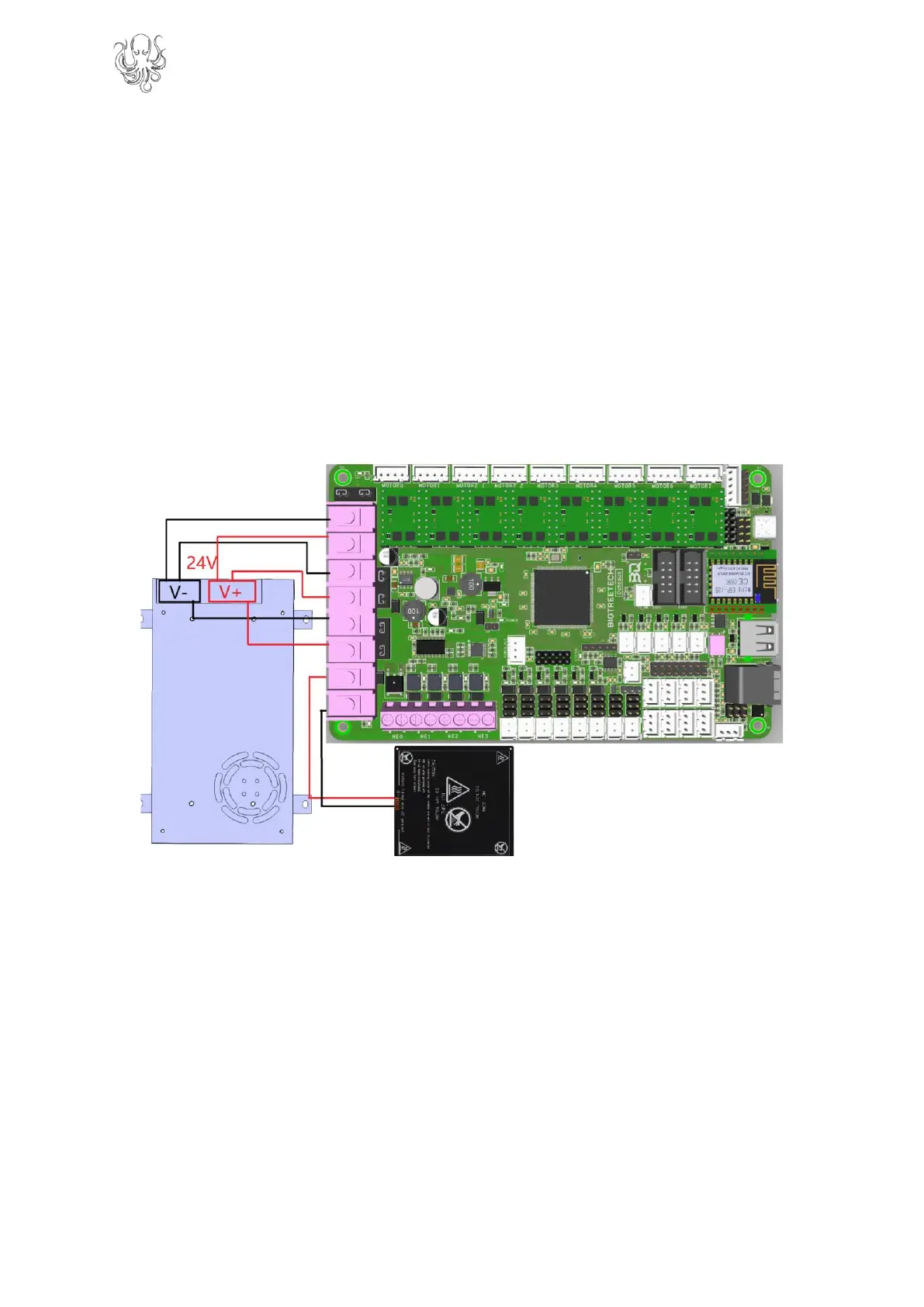
Power wiring is as shown below (look on the underside of your board to identify the purpose
of each input). The positive (red) wire from the power supply goes to the terminal marked +.
The negative (black) wire from the power supply goes to the terminal marked -. The polarity
(+ and -) is also silk screened onto the underside of the board as a convenience to the user.
Note: DO NOT alter the board wiring with the power on and be sure to get the
polarity correct, otherwise you can cause damage to the motherboard.
2.2 AUTOMATIC POWER DOWN WIRING
When using the BIGTREETECH Relay V1.2 module, the wiring can be performed as shown
in the figure below.
 Loading...