10
Motor Installation
1. Remove the plastic casing from the motor (A).
2. Connect the motor to the base using the M8 bolts (P)
withtheirspring(V)andatwashers(T)andnuts(R).
Adjust the placement of the bolts in their slots to match
the expected path of the chain as shown. Normally, the
path of the chain will be 1¼ to 1½ inches (32–39 mm)
from the inner edge of the gate.
3. Remove the protective cover from the motor circuit board. Keep its fasteners nearby.
NEVER make electrical connections while the motor’s power supply is active. Disconnect
the GFCI or circuit breaker before any wiring adjustment.
4. You will need to directly wire your power source into the motor’s
circuit board. Connect the provided cord or your extension to the
main power terminal, the only one with three pin positions. Use
a small athead screwdriver to loosen and tighten the terminal
screws as needed. Connect the ground wire to the top PE pin, the
live wire to the central L pin, and the return or neutral wire to the
bottom N pin. Be sure no wiring is left bare and exposed.
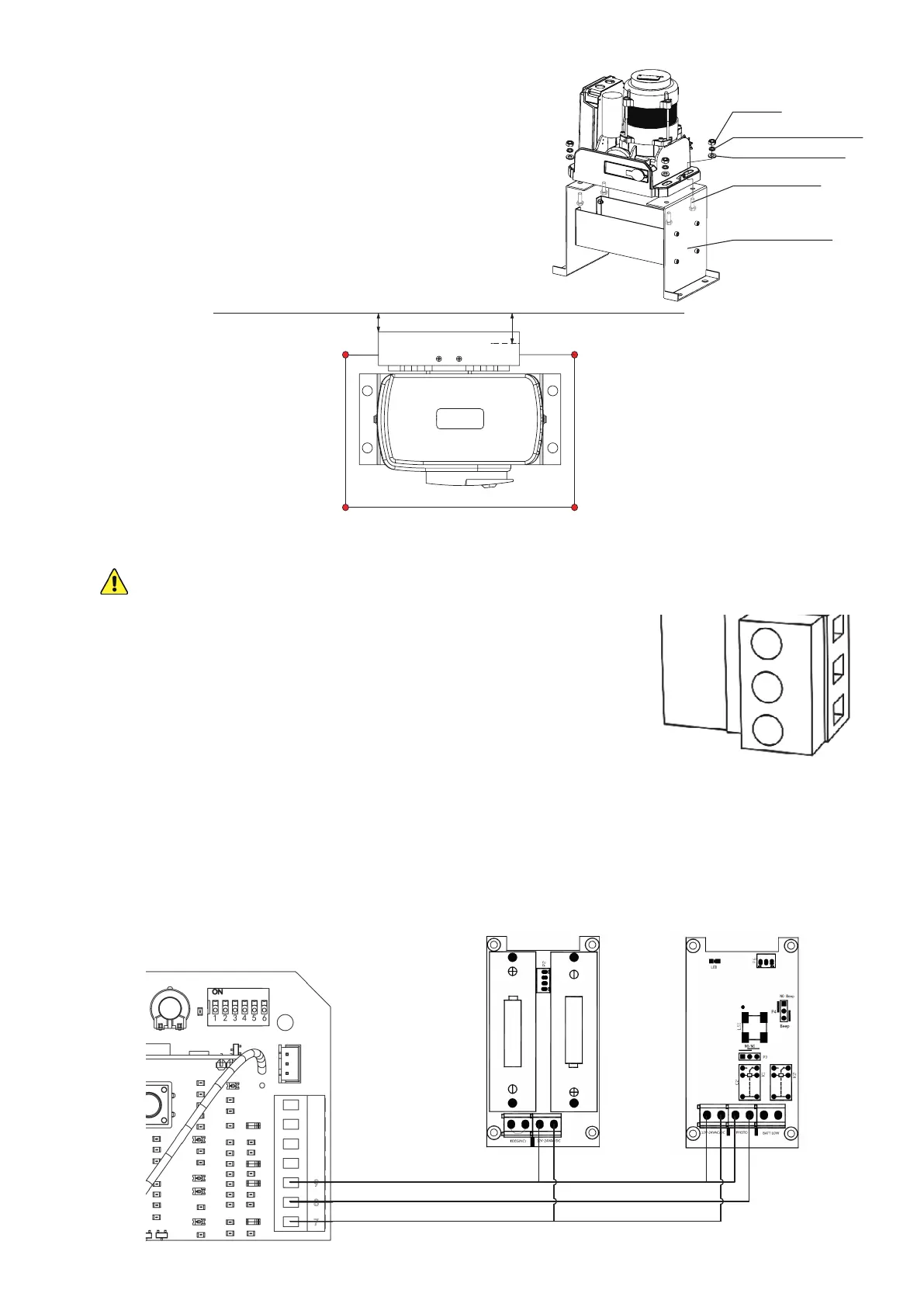
5. If you will be using the provided infrared sensors, nd the long terminal next to the circuit
board’s DIP switches. Remove the wire shorting pins 8 and 9 together. Connect the wiring from
your infrared sensors as shown. The sensors’ power input pins should be connected to the
bottom +15V pin (7); the receiver’s photocell signal pin should be connected to the central NC
pin (8); and the sensors’ power return pins and the receiver’s photocell return pin should all be
connected to the top GND pin (9).
0.67–0.82 in.
(17–21 mm)
1.25–1.54 in.
(32–39 mm)
M8 Flat Washer
M8 Nut
M8 Spring Washer
M8×40 Bolt
Mounting Base
PE
L
N
Transmitter Receiver