Manual for VMP300-based instruments
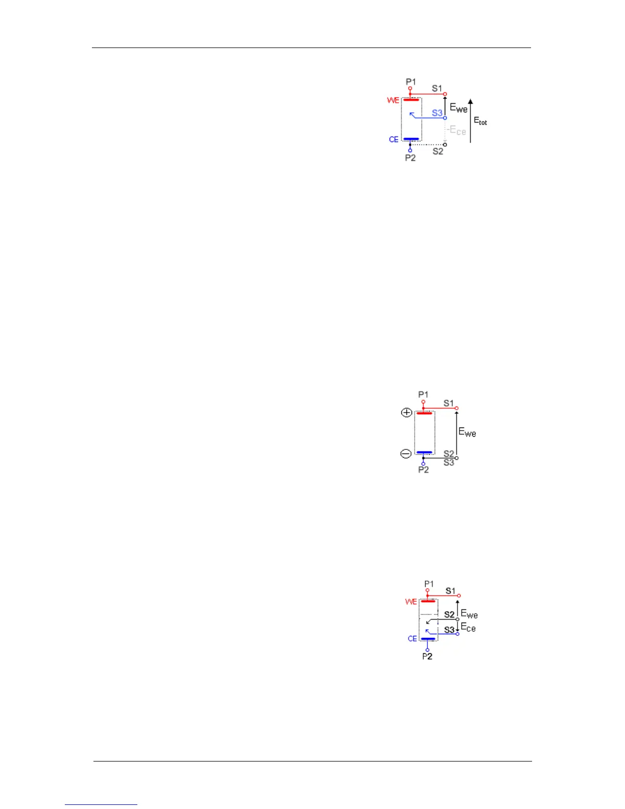
Another three-electrode connection with a
reference electrode can be done, for example in
battery applications. This connection allows the
user to record/control the positive and negative
electrodes of the battery simultaneously. For this,
the following connection has to be done:
- Connection of the positive
electrode (WE) to S1+P1,
- Connection of the negative
electrode (CE) to S2+P2,
- Connection of the reference
electrode (REF) to S3.
Fig. 61: Alternative three-electrode
connection.
In the instrument, potential regulation is done between S1 and S2. Therefore, the total potential
of the battery will be displayed by default. The other parameters, such as the potential of the
positive and the negative electrodes versus the reference electrode, can be displayed by
ticking the boxes E
ce
and E
we
-E
ce
in the “Cell Characteristics” window.
In the data file, the following rows will be displayed:
- E
we
related to S1-S2 i.e. total potential of the battery,
- E
ce
related to S3-S2 i.e. – negative electrode potential vs. Reference,
- E
we
- E
ce
related to S1-S3 i.e. positive electrode potential vs. Reference
electrode.
It is then possible to plot the change of potential (positive, negative, total) as a function of time
or state of charge (SOC).
5.2.2.2 Two-electrode connection
In the two-electrode connection mode, the positive
electrode of the device of interest (battery, fuel cell,
supercapacitor, ….etc) is connected to S1+P1. The
potential control or measurement is performed
between S1 and S2, and the controlled or measured
current crosses the cell from P1 to P2. So the
negative electrode has to be connected to
S2+S3+P2. In order to study the positive battery and
negative electrode materials, the user inserts a
reference electrode. Then a three-electrode
assembly is required (refer to the previous part).
Fig. 62: Two-electrode connection
to a battery cell.
5.2.2.3 Four-electrode connection
In the four-electrode connection mode, the user has
the ability to record the liquid-liquid interface potential
(E
ce
), also called Kelvin probe connection.
In this connection mode, S1 should always be
connected to WE (or to the positive electrode) for
proper cell isolation. However, to avoid an IR drop in
connections, it is recommended to connect S1
directly to the cell electrode and not to the P1 cable.
Fig. 63: Four-electrode connecti-
on for a liquid – liquid interface.
 Loading...