78
8.1.3 Validation of the ultra-low current module.
The procedure is exactly the same. The only difference is that the cell cable connected to the
dummy cell will be the ultra-low current cell cable instead of the standard cell cable.
Moreover, the user can check if the instrument goes through the current ranges of ULC (1A to
1pA) option. To check this, the user has to decrease the scan rate and check the current range
indicated in the status bar. For the current range 10pA and 1pA an analog filter (50 kHz,1 kHz
or 5 Hz) should be activated.
8.1.4 Validation of the booster board
For the booster board validation, the procedure is similar to the procedure described in II.1.
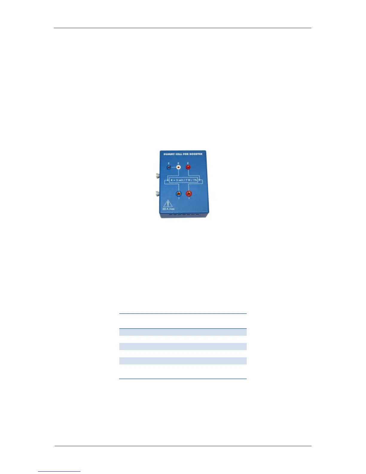
Because of the involved current, the dummy cell, DC2, has to be exchanged by the dummy
cell for booster (Fig.114).
Fig. 114: Dummy cell for boosters.
The voltage sweep, i.e. E1; E2 and Erange parameters of the CV technique, has to be set
according to the specifications of the dummy cell and the booster. Some examples are given
in Tab. 9.
For your information, the specifications of the dummy cell for booster are:
5 mΩ (Accuracy: 1%)
P
max
= 7 W
I
max
= 20 A.
Table 9: The E1, E2 and Erange values according to the booster type.
Moreover, the user can check if the instrument goes through the current ranges of the booster.
To check this, the user has to check the current range indicated in the status bar.