Fig. 112: Equivalent circuit selection.
- Click on the “Minimize” button (Fig. 113).
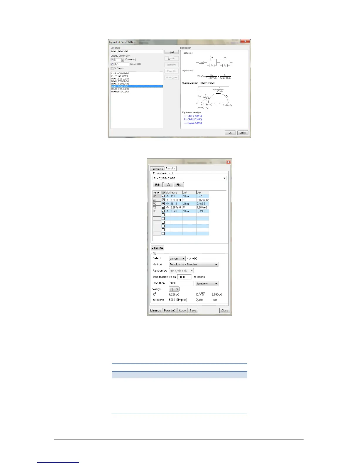
Fig. 113: Results of Z Fit.
- Check the fitted values. They have to be close to the theoretical values. The theoretical
values for DC2 are summarized in Tab. 8.
-
Table 8: The theoretical values of the DC2.
 Loading...