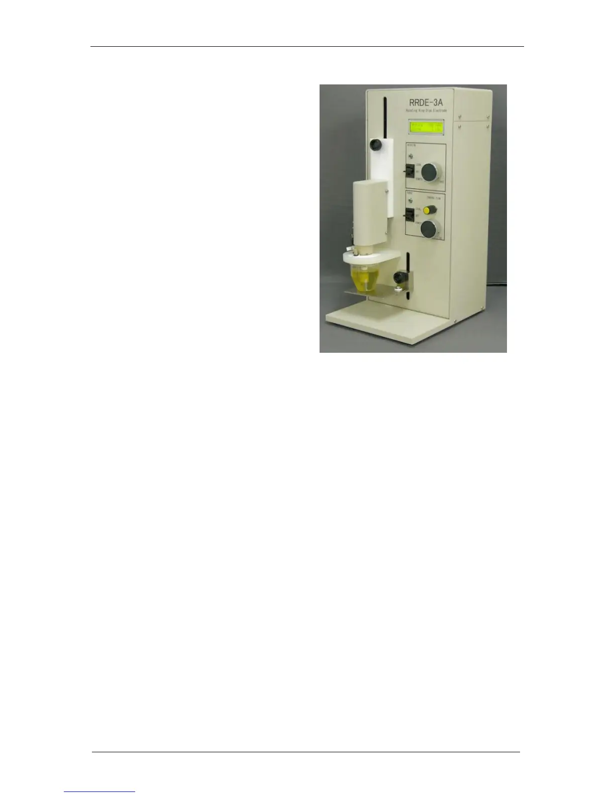
The Bio-Logic instrument can control a
rotating electrode such as a ALS-RRDE-3A
Rotating Disk electrode model with the
auxiliary input/output. A specific control
panel has been designed to control the
rotation speed.
Note that no measurement of the actual
rotation speed is available with the ALS-
RRDE-3A model.
6.4.2.1 Connections
Two cables are necessary for connection of a rotating disc electrode, the cell cable and a
special cable for RRDE with a DB-9 connector. This cable has a DB9 connector on one end
and three wires named Analog Out, Trigger Out and 1 Ground on the other end (PN: 092-
22/11).
The connection procedure is as follows:
Connect the DB9 cable to the front of the channel board (Auxiliary Input/Output).
Connect the “Analog Out” wire to the “IN” plug on the rear panel of the RRDE-3A.
Connect the “Ground” wire to the “GND” plug on the rear panel of the RRDE-3A.
To control the purge of the RRDE-3A, connect the “Trigger Out” to the “Purge” plug on
the rear panel of the RRDE-3A.
Connect the REF1 and CA2 wires to the disk brush, REF3 and CA1 wires to the counter
electrode, and REF2 wire to the reference electrode. For RRDE experiment, “CE to
Ground” mode must be selected. In that case, use the appropriate connections for both
the ring and the disc channels.
 Loading...