Manual for VMP300-based instruments
74
8. Validation and calibration
8.1 Channel validation
The channel board is the potentiostat/galvanostat board alone (not connected to any Low
Current option or current boosters)
Actually, there are two procedures depending
on the board option:
The first one can be done for every channel
board,
The second one can only be done for boards
with the EIS option
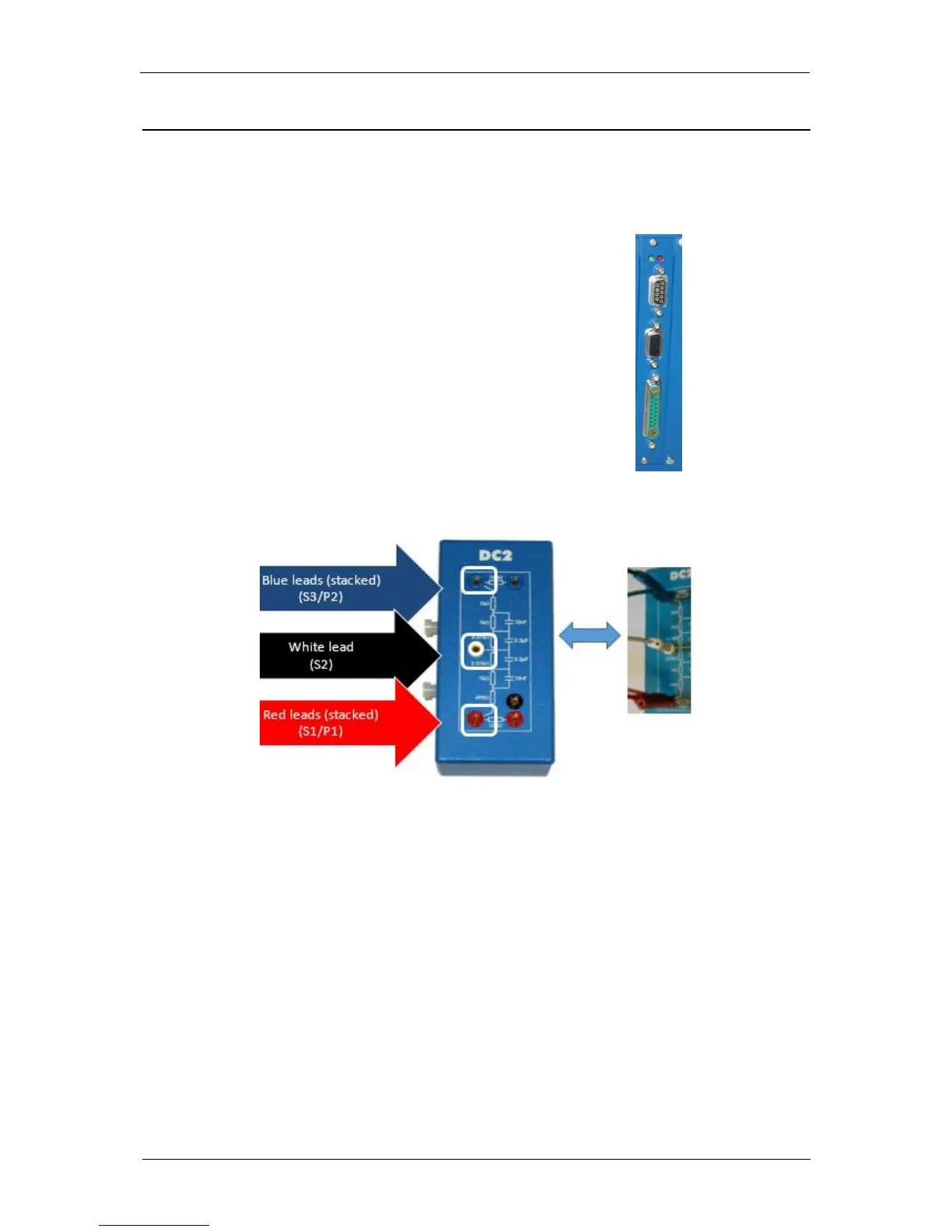
For both procedures, the user needs a dummy
cell (DC2) shown in Fig. 106. This is the dummy
cell provided with each channel board. The cell
cable has to be connected as shown in the
Fig. 106.
Fig. 106: Front panel of a channel board
of VMP300-based instruments.
Fig. 107: Connection of the cell cable to the Dummy cell (DC2).
Note:
The two blue leads have to be stacked together and the two red leads have to be stacked together.
CAUTION
It is noteworthy that to avoid any external perturbation, the dummy cell has to be placed in a
Faraday cage. This Faraday cage has to be connected to the chassis of the instrument (green
plug on the rear panel).