EasyManuals Logo

Bio-Logic SP-300 User Manual

Default Icon
122 pages
To Next Page IconTo Next Page
To Previous Page IconTo Previous Page
Page #75 background imageLoading...
Page #75 background image
Manual for VMP300-based instruments
67
With the IS1, even if the channel is
connected to an external device, it keeps its
floating character.
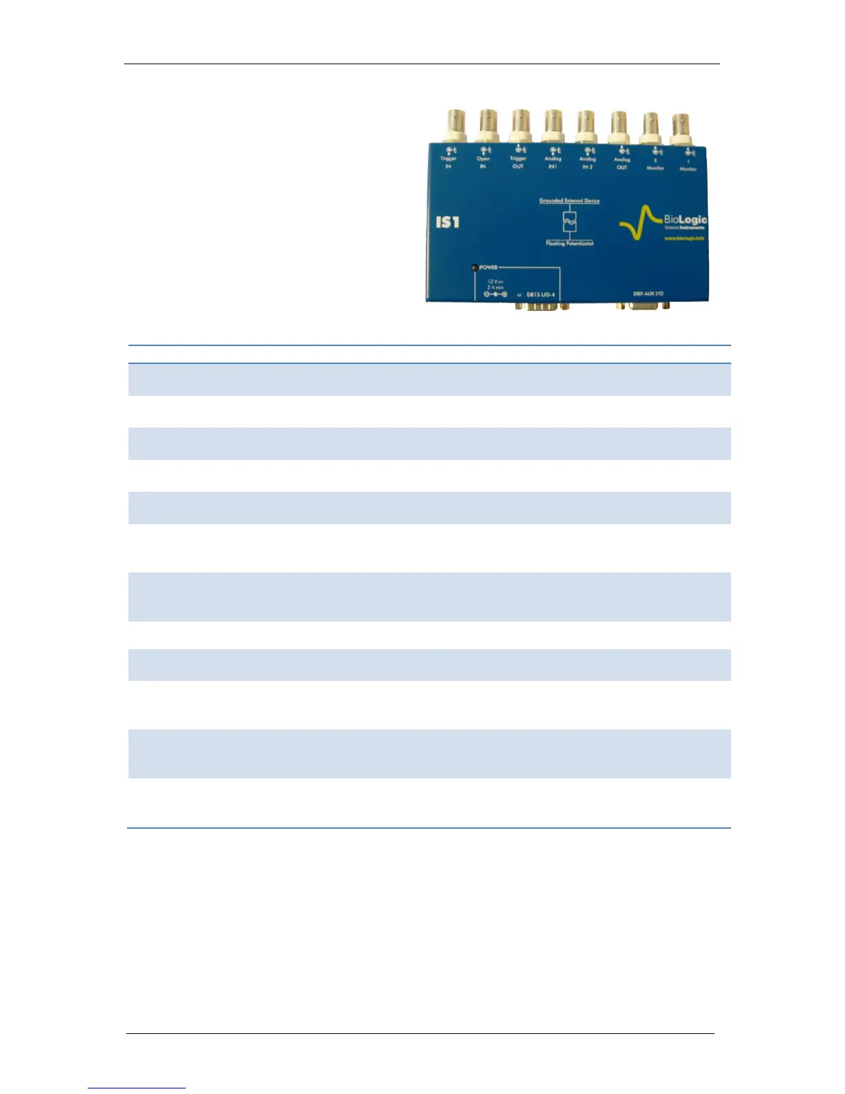
The IS1 is powered by the potentiostat
board using the LIO cable connected to the
DB15 (or SubD 15) connector on the
potentiostat or by an external 12V DC
power supply. The auxiliary cable from the
potentiostat board is connected to the DB9
connector on the IS1.
The external device is connected to the IS1
thanks to a simple BNC cable. All the
available I/O were separated in the same
manner as the DB9 to BNC adaptor.
Fig. 94: IS1 option.
IS1 specifications:
Analog I/O
Digital I/O
Input (IN1, IN2) :
Input (Trigger In, Open In):
Input impedance:
>10
11
Ω / 15 pF
Input impedance
1 MΩ / 150 pF
Input voltage range:
+/- 10 V
Input voltage range
0 to 5 V
Bandwidth
50 kHz
Input frequency max
400 kHz
Signal noise:
10 mV
pp
(peak to
peak)
Low/high
input threshold
[0; 0.8]V / [2 ; 5] V
Maximum propagation
time/Minimum pulse
width
1 µs
Output (Out , I monitor, E monitor) :
Output (Trigger Out):
Output impedance
100 Ω
Output impedance
100 Ω
Signal noise
10 mV
pp
Low/high
input threshold
[0; 0.4] V / [4.6; 5] V
Output current max
10 mA
Maximum output
frequency:
400 kHz
Maximum propagation
time/Minimum pulse
width
1 µs

Table of Contents

Questions and Answers:

Question and Answer IconNeed help?

Do you have a question about the Bio-Logic SP-300 and is the answer not in the manual?

Bio-Logic SP-300 Specifications

General IconGeneral
BrandBio-Logic
ModelSP-300
CategoryMeasuring Instruments
LanguageEnglish

Related product manuals