10
7.3 Attaching head
1) Polisher must be disconnected from a turbine
hose of dental unit when attaching and
detaching the head. If it is connected,
disconnect from the turbine hose fi rst.
2) Confi rm the o-ring of the head is not
damaged.
3) If water, oil, or powder adheres to head or
inside the chamber unit’s coupling, wipe off
with a cotton swab or dry cloth.
4) Align the head to the thread of the chamber
unit’s coupling, turn the head in the direction
of the arrow in the illustration until it stops.
Confi rm secure attachment.
Remove water,
oil, and powder.
Confirm the o-ring of the head
is not damaged.
11
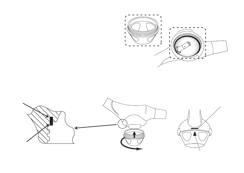
7.4 Attaching powder cap
* Water due to sterilization must be expelled
by an idle run beforehand. Do not fi ll the
powder yet.
1) The powder cap must be attached or detached when
polisher is not connected to a turbine hose. If
connected, detach from the turbine hose.
2) If water, oil, or powder adheres to inside chamber unit,
powder cap, or powder seal, wipe off with a dry cloth.
3) Confi rm the powder seal (blue) is fully engaged in the
groove of chamber unit shown in the illustration.
4) Turn the powder cap in the direction of the arrow in
the illustration until it stops. Confi rm the powder cap is
fi rmly attached and the triangle symbol on the powder
cap lies within the range of the mounting position mark.
In case the triangle symbol lies outside of the mounting
position mark, replace your powder seal with new one
according to “10.4 Replacement of powder seal”.
Remove water, oil,
and powder.
Enlarged sectional view
Groove
Powder seal
Mounting position mark
Triangle symbol
11
7.4 Attaching powder cap
* Water due to sterilization must be expelled
by an idle run beforehand. Do not fi ll the
powder yet.
1) The powder cap must be attached or detached when
polisher is not connected to a turbine hose. If
connected, detach from the turbine hose.
2) If water, oil, or powder adheres to inside chamber unit,
powder cap, or powder seal, wipe off with a dry cloth.
3) Confi rm the powder seal (blue) is fully engaged in the
groove of chamber unit shown in the illustration.
4) Turn the powder cap in the direction of the arrow in
the illustration until it stops. Confi rm the powder cap is
fi rmly attached and the triangle symbol on the powder
cap lies within the range of the mounting position mark.
In case the triangle symbol lies outside of the mounting
position mark, replace your powder seal with new one
according to “10.4 Replacement of powder seal”.
Remove water, oil,
and powder.
Enlarged sectional view
Groove
Powder seal
Mounting position mark
Triangle symbol