Overview of BFM-900L
17
BFM-900L
FETAL MONITOR
(
Ver 1.1
)
16
Overview of BFM-900L
3.4 Symbols
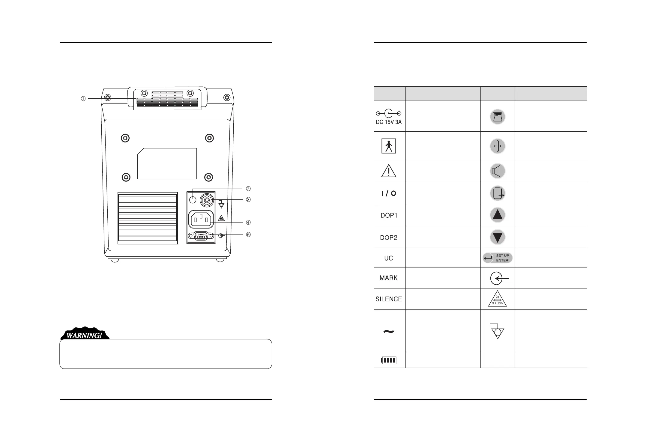
■Rear Face
(1) Handle for Carriage (2) Adapter Power Connection Part
(3) Ground Terminal (4) AC Power Connection Part
(5) RS-232C Cable Connection Part
Do not disassemble the device. Otherwise, you may be electrically shocked. The device shall
not be disassembled by other than the person qualified for our product service.
Symbol Description Symbol Description
15V-3A DC Power Input
Type BF Device,
Electric Shock Device
Protection
Warning or Precaution
(See the User s Manual.)
AC Main Power On/Off
DOP1 Probe Connection Part
DOP2 Probe Connection Part
UC Probe Connection Part
Mark Jack Connection Part
Ethernet Connection Terminal
Working by AC Input
Working by Battery
Print Start/End
UC Reference Setting
Display
Volume Control
Back to Default Screen (Exit)
Setting Change
Setting Change
Save the Setting
Back to Menu mode
DC Communication Port
AC Power Input Part
Terminal for Equipotent by
Connection of Each Part of
Device/System without
Necessity of Ground
Potential