2
3
1
4
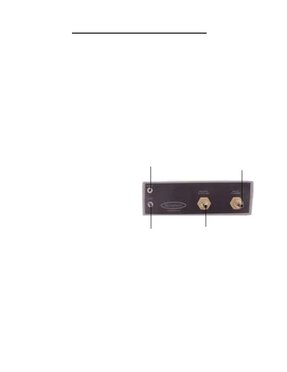
1. Power Supply
Plug the 12VDC regulated power sup-
ply into a wall outlet. Then plug the jack end
into the port labeled “12VDC” on back of the
Proox 360. The display on the front of the
Proox 360 should turn on.
2. Connecting Gas
Attach 1/4 in. ID tubing, coming from
the compressed gas source, to hose barb
labeled “GAS SUPPLY 40 P.S.I.G. MAX” on
the back of the Proox 360. Making sure that
the gas coming in never exceeds 40 PSIG
or damage will occur to the Proox 360.
3. Connecting Infusion Tube
Attach 1/4 in. infusion tube to “GAS
OUT TO CHAMBER” barb on back of the
Proox 360. Route the infusion tubing to the
chamber. If you need to reduce the size of
the tubing to 1/8 in. ID, use the provided gas
fitting. Attach the supplied gas fitting to the
infusion tube and attach the short piece of
1/8 in. ID tubing to the other end of the gas
fitting. This will attach to the chamber.
4. Connecting Sensor
Plug the jack end of the sensor cable
into the port labeled “SENSOR” on back of
the Proox 360. Plug the other end of the
sensor cable into the sensor itself by lining
up the key on the terminal with the key on
the connector of the sensor cable. Push in
and twist the ring on. The display on the
front of the Proox 360 should respond.
Proox 360 Back Panel Installation
8
Proox model 360
version 1.0
The following steps will explain how to set up the back of the Proox
360 and prepare it for installation to a chamber.