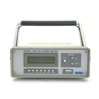
Bird 4421 RF Power Meter
8
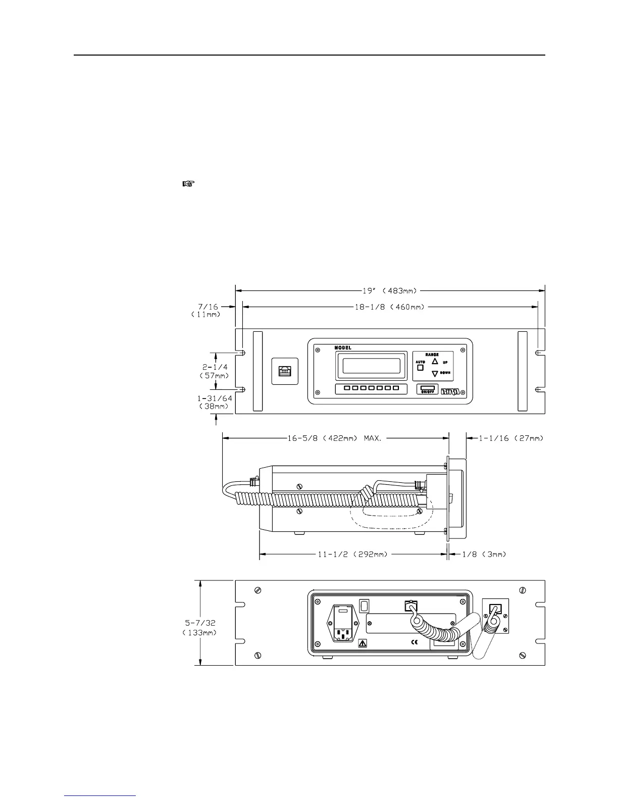
Panel Mounting the 4421 Power Meter
You can install the 4421 Power Meter in an equipment rack if you have the
optional panel mount kit (refer to Op
tional Accessories, page 1). The panel
mount kit includes comple
te installation instruct
ions. Figure 5 shows the
overall dimensions and mounting points
for a 4421 Power Meter installed in a
panel mount kit.
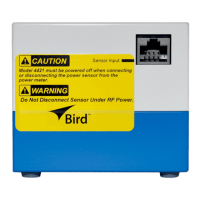
Note:
The power supply interrupt switch
for the 4421 Power Meter is
located on the rear panel. When you in
stall a unit in a panel mount kit, you
need to provide a means to interrupt the
power supply that is
easily accessible
to the user (such as a swit
ch mounted in the panel).
Figure 5 Panel Mounting Dimensions
RF POWER METER
dBm
MAX LIGHT
SWRMIN
RFL
4421
FWD
SENSOR
POWER
1
7
8
-
2
6
4
V
A
C
VOLTAGE
1
0
0
-
1
3
2
V
A
C
A
T
4
7
.
5
-
6
6
H
z
M
A
X
I
M
U
M
P
O
W
E
R
1
5
W
R
E
M
O
V
E
A
C
P
O
W
E
R
B
E
F
O
R
E
A
T
T
E
M
P
T
I
N
G
T
O
S
E
R
V
I
C
E
T
H
I
S
I
N
S
T
R
U
M
E
N
T
.
W A R N I N G
T
.
1
2
5
A
,
2
5
0
V
T
.
2
5
0
A
,
2
5
0
V
F
U
S
E
AC SUPPLY
O OFF
FUSE
I ON
POWER
SENSOR
 Loading...