Maintenance
43
Functional Test
This test determines whether the powe
r meter or the sensor is malfunction-
ing.
1. Turn the power meter off.
The ON/OFF switch on the
panel should be
OFF and the ac power cable should be connected.
2. Turn ON the ON/O
FF switch on the
panel of the meter.
3. While holding down the FWD and
SWR push buttons, press the ON/OFF
button on the
panel of the power mete
r. Immediately release all
three.
The unit tests the display on power up cycling through and activat-
ing each segment two times and th
en activating all segments at
once two times.
vision date shou
ld scroll across
layed instead, th
en the meter is
malfunctioning.
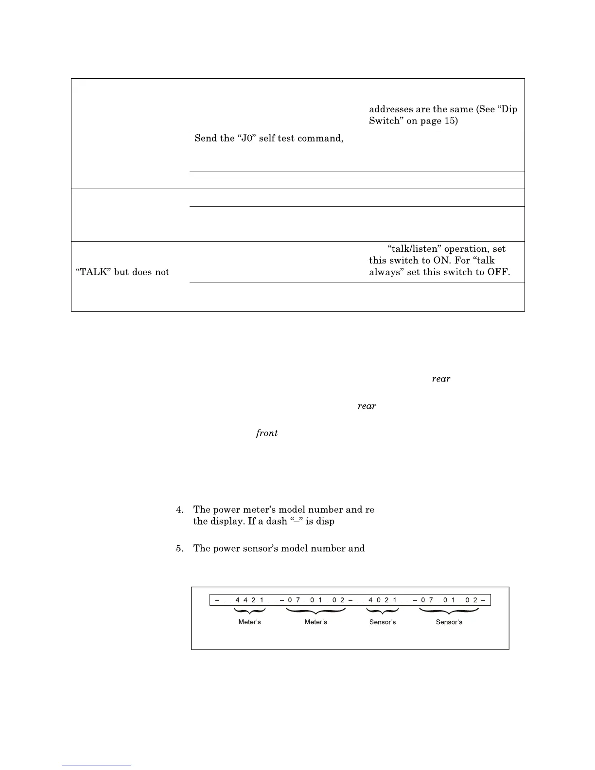
revision date should scroll across
the display. If a dash
is displayed after the po
wer meter data, then the
power sensor is malfunctioning.
IEEE-488 Interface
does not respond to the
interface link
Are the address in the interface
program and the address setting on
the DIP switches on the interface
module the same?
Change the program or DIP
switch setting so that the
then check the status. Does the
power meter fail the self test?
Replace I/O hub PCB
Is the IEEE cable defective? Replace IEEE interface cable
RS-232 Interface does
not respond to the
interface link. Fails J 0
self-test command.
Are the DIP switches set correctly? Set DIP switches
Is the RS-232 cable defective? Replace RS-232 interface cable
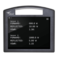
With the RS-232, the
power meter displays
operate as expected.
Is DIP switch 2 set correctly? For
Is DIP switch 1 set correctly? Set DIP switch 1 as indicated in
Figure 25
Figure 35
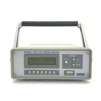
Test Display,
No Malfunction
Model
Number
Software
Rev. Date
Model
Number
Software
Rev. Date
 Loading...