29
Chapter 5
RS-232 Interface
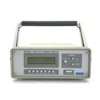
This chapter discusses setup of the RS-232 interface feature and describes the
RS-232 commands that apply to the Bird 4421. Operators should understand
EIA Standard RS-232-C and have basic computer programming skills before
writing any programs.
Description
The Bird 4421 RS-232 interface feature is an integral part of the I/O hub cir-
cuit board inside of the mm21. An eigh
t-position DIP switch
is used to set
operational conditions such as baud rate, parity, and stop bits. The bottom
line of the display indica
tes the current bus status.
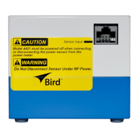
Cable Connector
The interface uses a standard 25-pin RS-232 connector. Pin assignments are
listed in Figure 24. If the controller us
es a different wiring arrangement, do
not attempt to rewire th
should be used for rewiring instead.
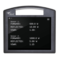
Indicators
splay shows indicato
rs describing the
status of the Bird 4421 when used
with the RS-232 interface. These are:
TALK:
When TALK is displayed, the power
meter is transmitting data. This
is always shown when the unit
LISTEN:
When LISTEN is displayed, the power meter is receiving data.
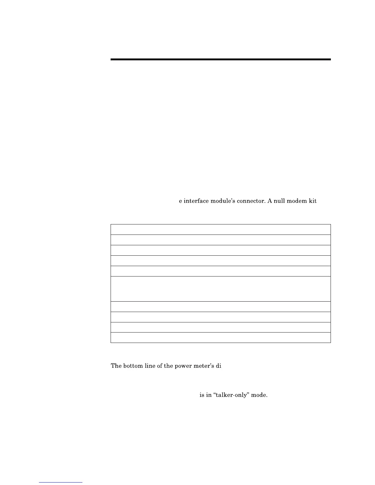
Figure 24
RS-232 Pin
Assignments
Pin Designation Notes
1 Protection Ground Chassis Ground
2 Transmit Data
3 Receive Data
4 Request to Send (Output) Set true after module power up
5 Clear to Send (Input) Set by input device. When true, it
enables the module to transmit. When
false, it disables transmission.
6 Data Set Ready (Input) Set internally true by module
7 Signal Ground Return path for data and control signals
8 Receive Signal DET (Input) Set true by module
20
Data Terminal Ready (Output) Set true after module power up
 Loading...