KB-206-18
Component Scope of delivery
Stand. Opt.
1 Compressor, semi-hermetic x
1a Discharge gas shut-off valve x
1b Suction gas shut-off valve x
2 Condenser, air-cooled x
2a Condenser fan x
3 Condensate line x
4 Liquid receiver x
4b Ball valve x
5a Terminal box/controller of
the condensing unit
x
6 Discharge gas line x
8 Oil separator x
8a Oil monitoring OLC-K1 x
9 Check valve x
10 Liquid line x
11 Filter drier x
12 Sight glass x
13 Suction gas line (insulated) x
18 HP limiter/ HP cut-out x
19 LP limiter x
22 Discharge gas temperature
sensor
x
23 Suction gas temperature
sensor
x
25 CRII capacity control
1 x standard for
LHL3E/2EES-2Y ..
LHL5E/4CES-6Y
1 x standard + 1 x option for
LHL5E/4FES-3Y ..
LHL5E/4CES-6Y
x x
26 Ambient temperature sensor x
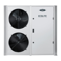
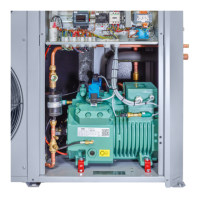
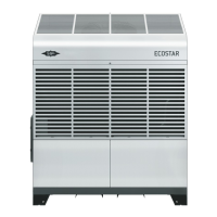
Tab.2: Legend and state of delivery ECOLITE condensing units
5 Application ranges
Permitted refrigerant R134a, R404A, R407A,
R407C, R407F, R448A,
R449A, R450A, R507A,
R513A, R22
Oil charge ① t
c
< 70°C BITZER BSE32
Maximum allowable pres-
sure (PS)
LP: 19 bar, HP: 32 bar
Maximum permitted ambi-
ent temperature
-20°C .. +50°C
For application limits, see brochure KP-104 or BITZER
software.
① For alternative oils, see Technical Information
KT-510.
WARNING
Risk of bursting due to counterfeit refrigerants!
Serious injuries are possible!
Purchase refrigerants only from reputable man-
ufacturers and reliable distributors!
5.1 Maximum allowable pressure
The whole system must be designed and operated
such that the maximum allowable pressure (PS) cannot
be exceeded in any part of the system (see name plate
details).
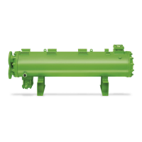
Pressure relief valves on receivers (pressure vessels)
are absolutely necessary if:
• it is to be expected that the maximum allowable
pressure will be exceeded due to external heat
sources (e.g. fire).
• the entire refrigerant charge of the system is more
than 90% of the pressure vessel volume at 20°C (ca-
pacity). The vessel volume is defined as the volume
between the valves upstream and downstream of a
pressure vessel lockable during normal operation.
• the entire refrigerant charge of the system is more
than 90% of the pressure vessel volume at 20°C (ca-
pacity). The vessel volume is defined as the volume
between the valves upstream and downstream of a
pressure vessel lockable during normal operation.
• a check valve is located between condenser and re-
ceiver.
Safety switching devices
According to local regulations, additional pressure-limit-
ing safety devices must be provided.