INT389R – monitoring functions
The terminal and contact designations
used in the following description refer
to the wiring diagrams in chapter 5.5.
Connect the measuring leads to ter-
minals 1/2/3.
Temperature monitoring
• PTC sensors in motor winding and
discharge gas outlet:
The INT389R locks immediately, if
the max. permissible temperatures
are exceeded.
• The control signal (11/14) is inter-
rupted.
- Signal contact 12 (fault indicator
H1) blinks with an on/off ratio of
1:3.
- Simultaneously, lamp H2 lights up
permanently (via signal contact
24, pause).
• Manually reset the protection
device when the compressor has
cooled down.
INT389R – fonctions de contrôle
Les désignations des bornes et contacts
utilisées dans la description ci-après, se
réfèrent aux schémas de principe du cha-
pitre 5.5.
Raccorder les fils de mesure aux bornes
1/2/3.
Contrôle de la température
• Résistances CTP dans bobinage
moteur et en sortie du gaz de refoule-
ment:
L'INT389R verrouille immédiatement,
si les températures maximales
admises sont dépassées.
• Le courant de commande (11/14) est
interrompu:
- Le contact signal 12 (lampe panne
H1) clignote suivant le rapport allumé
/ éteint 1:3;
- Simultanément, la lampe H2 est allu-
mée en permanence (par le contact
signal 24, pause).
• Après refroidissement du compres-
seur, déverrouiller manuellement le
dispositif de protection.
INT389R – Überwachungsfunktionen
Die in der folgenden Beschreibung
verwendeten Klemmen- und Kontakt-
Bezeichnungen beziehen sich auf die
Prinzipschaltbilder Kapitel 5.5.
Messleitungen an Klemmen 1/2/3
anschließen.
Temperatur-Überwachung
• PTC-Widerstände in Motorwicklung
und Druckgasaustritt:
Das INT389R verriegelt sofort,
wenn die maximal zulässigen Tem-
peraturen überschritten werden.
• Steuerstrom (11/14) wird unterbro-
chen.
- Signalkontakt 12 (Störmelder H1)
blinkt im Ein-/Aus-Verhältnis 1:3.
- Gleichzeitig leuchtet die Lampe
H2 permanent (über Signalkon-
takt 24, Pause)
• Schutzgerät manuell entriegeln
nachdem der Verdichter abgekühlt
ist.
46 SH-100-3
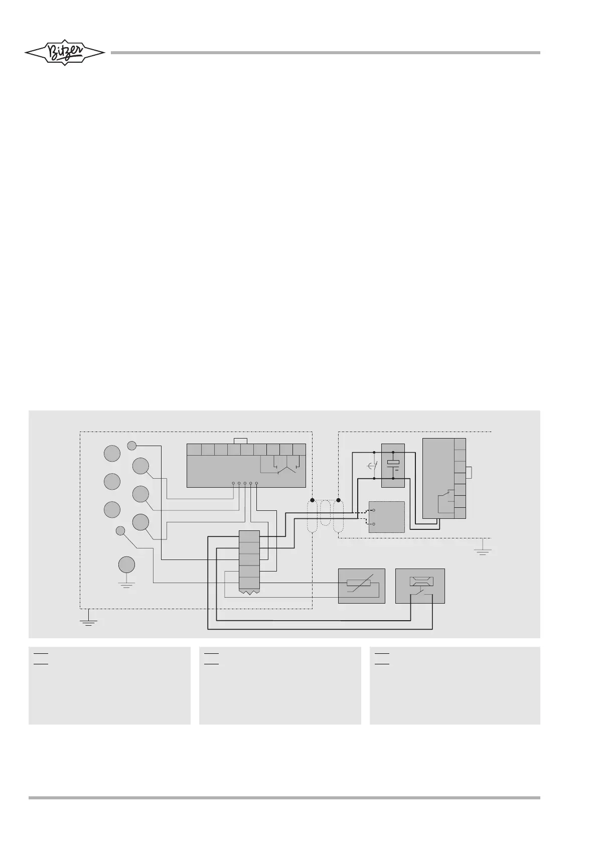
Abb. 22 Elektrischer Anschluss von
INT389R im Anschlusskasten und
im Schaltschrank SE-B2 oder
alternativ OFC
Fig. 22 Electrical connection of INT389R
in terminal box and in switch board
SE-B2 or alternatively OFC
Fig. 22 Raccordement électrique du INT389R
dans la boîte de raccordement et dans
l'armoire électrique
SE-B2 ou OFC comme alternative
 Loading...