6
3.3 Direct drive by coupling
Safety note!
Observe safety standards
EN 294 / EN 349 and national
regulations.
Only designs of coupling with flexible
transmission elements may be used,
which can compensate for slight axial
displacements, without themselves
exerting any axial force. The BITZER
coupling KS 620/720/730 meets these
conditions.
Connection of the compressor to the
motor by the coupling housing (see
Fig. 2):
• Clean the fitting surfaces on com-
pressor, motor and coupling housing
• Fit the motor on the rails
• Slide the coupling half for the
motor (including key) loosely on the
motor shaft, fit the coupling hous-
ing on the motor
• Slide the coupling half for the com-
pressor side (including key) flush
on the compressor shaft and tight-
en, fit the compressor onto the
coupling housing
• Remove the safety grill from the
coupling housing, slide the coupling
half for the motor side until the play
is 2..3 mm and tighten
!
!
3.3 Azionamento diretto mediante
giunto
Avvertenza per la sicurezza!
Prestare attenzione alle norme di
sicurezza EN 294/EN 349 e alle
norme nazionali.
Sono consentite come giunti solo versioni
con elementi intermedi elastici che sono
in grado di compensare lo spostamento
ridotto in direzione assiale senza eserci-
tare alcuna forza assiale. I giunti BITZER
KS 620/720/730 soddisfanno tale condi-
zione.
Il compressore è collegato al motore
attraverso la custodia del giunto
(vedi fig. 2):
• Pulire le superfici di contatto sul com-
pressore, sul motore e sulla custodia
del giunto
• Posizionare il motore sulle guide
• Posizionare la parte del giunto per il
lato del motore (compresa la linguetta
di aggiustamento) sull'albero motore
senza fissarla, fissare la custodia del
giunto sul motore
• Posizionare la parte del giunto per il
lato del compressore (compresa la lin-
guetta di aggiustamento) in modo alli-
neato sull'albero del compressore e
avvitarla, fissare il compressore sulla
custodia del giunto
• Rimuovere la griglia di protezione sulla
custodia del giunto, spostare la parte
del giunto sul lato del motore finché il
gioco ammonta a 2..3 mm, poi avvitar-
la
3.3 Direktantrieb durch Kupplung
Sicherheitshinweis!
Sicherheitsnormen EN 294/
EN 349 sowie nationale Vor-
schriften beachten.
Als Kupplung nur Bauarten mit elasti-
schen Zwischenelementen verwen-
den, die geringe Verschiebungen in
Axialrichtung ausgleichen können,
jedoch selbst keine Axialkraft ausü-
ben. Die BITZER Kupplungen
KS 620/720/730 erfüllen diese
Bedingungen.
Der Verdichter wird über Kupplungs-
gehäuse mit dem Motor verbunden
(siehe Abb. 2):
• Passflächen an Verdichter, Motor
und Kupplungsgehäuse reinigen
• Motor auf Schienen aufstellen
• Kupplungshälfte für die Motorseite
(einschl. Passfeder) lose auf die
Motorwelle schieben, Kupplungs-
gehäuse am Motor befestigen
• Kupplungshälfte für die Verdichter-
seite (einschl. Passfeder) bündig
auf die Verdichterwelle schieben
und festschrauben, Verdichter am
Kupplungsgehäuse befestigen
• Schutzgitter am Kupplungsgehäuse
entfernen, Kupplungshälfte auf der
Motorseite verschieben, bis Spiel
2..3 mm beträgt, dann festschrauben
SB-500-2 i
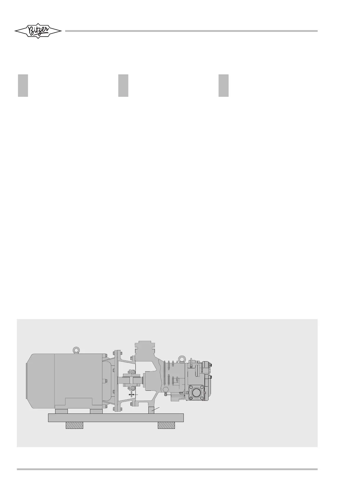
Abb. 2 Direktantrieb des Verdichters über
Kupplung
Fig. 2 Direct drive of the compressor by
a coupling
Fig. 2 Azionamento diretto del compressore
attraverso il giunto
1 Verdichter
Compressor
Compressore
2 Kupplungsgehäuse
Coupling housing
Custodia del giunto
3 Motor / Motor / Motore
4 Kupplung
Coupling
Giunto
5 Verbindungsschienen
Connecting rails
Guide di collegamento
6 zusätzliche Abstützung
additional support
supporto addizionale
7 Schwingungsdämpfer (bei Bedarf)
Vibration damper (if required)
Antivibrante (se necessario)