10
1. 8 7 7. 8 7 7. 2 269 BLACKBOX.COM
NEED HELP?
LEAVE THE TECH TO US
LIVE 24/7
TECHNICAL
SUPPORT
1.877.877.2269
2.5 HARDWARE DESCRIPTION
2.5.1 TOP PANEL (KV0004A-R2 VARIANT)
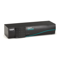
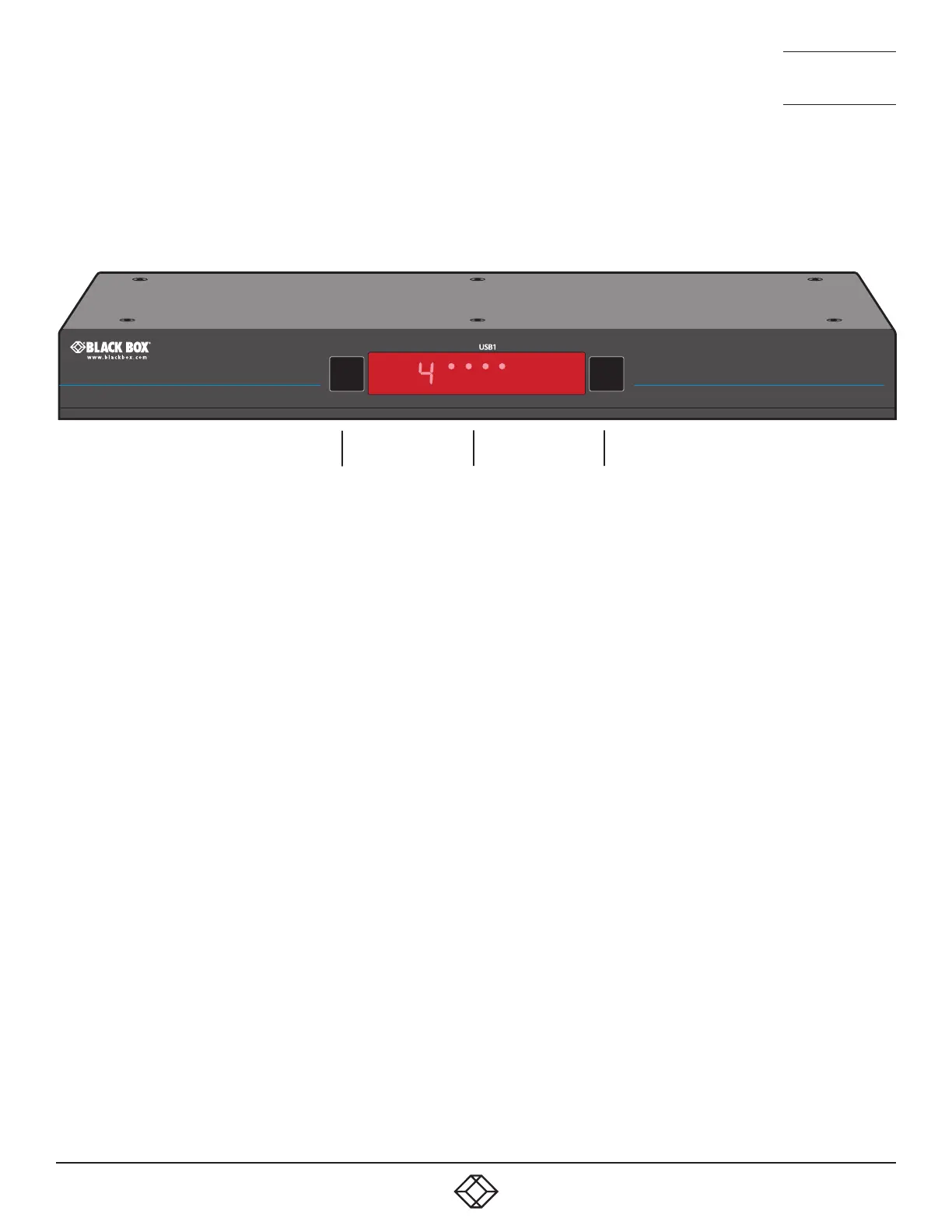
Figure 2-2 shows the top panel of the four-channel unit. Table 2-1 describes its components:
Figure 2-2. Top panel.
Table 2-1. Top panel components.
Number Component Description
1 Computer button Press to change to the next computer channel.
2 Indicators The lower four indicators (K/M, SPK, USB1, USB2) show which peripherals are switched
to the current computer channel or (as you begin pressing the Mode button) the
peripherals that will be switched during the next press(es) of the Computer button.
The upper four indicators scroll across at regular intervals whenever the Glide and Switch
channel switching system is enabled.
The seven-segment numeric display indicates the computer channel that is currently
active.
3 Mode button Press to determine which peripherals should be switched to another computer channel
(will occur when you press the Computer button).
1
2 3
Freedom II
ZERO-TOUCH DESKTOPSWITCH ING
Computer
K/M
SPK USB2 Mode
 Loading...