Technical Manual
2-2
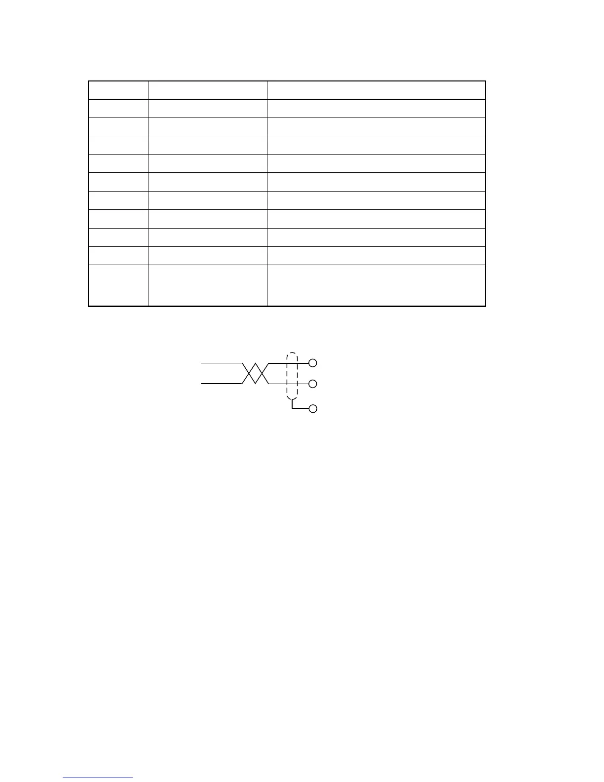
Profibus connector (DB9F)
Pin Signal Description
1 - -
2 - -
3 B line Positive RxD/TxD, RS485 level
4 RTS Request to send
5 GND Bus Ground (isolated)
6 + 5V Bus Output +5V termination power (isolated)
7 - -
8 A line Negative RxD/TxD, RS485 level
9 - -
Housing Cable shield Functional ground internally connected to the
module protective ground via cable shield
filters according to the Profibus standard.
For connection of the adaptor to the Profibus master, use a Profibus standard cable
and connector according to the diagram below.
For reliable fieldbus function, line termination must be arranged in both ends of the
transmission line. For a G5 instrument, at the end of the cable, a connector with line
termination should be used. For all other G5 Instruments, connection without line
termination should be used.
For configuration of the adaptor, a GSD file (VISH0F83.GSD) is available and should
be installed in the master.
Select the 8 words output module + 2 x 16 words input modules + one 8 words input
module. This will give 16 bytes of output data and 80 bytes of input data. The PLC set-
up should match this exactly including the order of the input modules.