Do you have a question about the BLH NOBEL G5 and is the answer not in the manual?
Covers essential safety guidelines for operating and servicing the instrument.
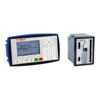
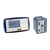
Defines the purpose and application of the G5 instrument family in industrial systems.
Details requirements for safe electrical installation, insulation, and grounding.
Describes G5 instruments (PM/RM) and their support for various Fieldbus interfaces.
Step-by-step instructions for correctly installing the Fieldbus module into the instrument.
Details the physical layout and LED indicators of the Profibus-DP module.
Explains the different states indicated by the Profibus-DP Operation Mode LED.
Explains the different states indicated by the Profibus-DP Status LED.
Guidance on using standard cables, termination, and GSD files for Profibus setup.
Describes the physical layout and LED indicators for the DeviceNet module.
Explains the different states indicated by the DeviceNet Network Status LED.
Explains the different states indicated by the DeviceNet Module Status LED.
Guidance on using standard cables and EDS files for DeviceNet setup.
Describes the physical layout and LED indicators for the ControlNet module.
Explains the states indicated by ControlNet Network Status LEDs A and B.
Explains the states indicated by the ControlNet Module Status LED.
Describes the physical layout and LED indicators for the EtherNet/IP module.
Explains the states indicated by the EtherNet/IP Network Status LED.
Explains the states indicated by the EtherNet/IP Module Status LED.
Explains the states indicated by the Link/Activity LEDs for EtherNet/IP ports.
Details instrument parameter control, storage, editing, and security.
Overview of parameters for setting up Fieldbus modules like Profibus, DeviceNet.
Settings for DeviceNet baud rate and IP parameters for EtherNet/IP.
Configuration of IP address, Net Mask, and Default Gateway for EtherNet/IP.
Choosing between Floating Point and Integer format for weight and other values.
Table showing the 8-byte output data mapping from network (PLC) to G5 Instrument.
Covers command bytes, parameter IDs, and data to write for output values.
Explains the difference in byte order for Profibus, DeviceNet, ControlNet, and EtherNet/IP.
Table detailing the 106-byte input data from G5 Instrument to network (PLC).
Register holding the overall error code for the instrument.
Explains bits in the Instrument Status register, including remote operation.
Defines codes for various instrument states like Starting up, Normal, Error.
Explanation of bytes used to acknowledge commands and report command errors.
Details bits indicating if weight is above defined levels 1 through 4.
Explains bits related to setpoint activation and cycle completion.
Details bits indicating the status of digital inputs and outputs.
Register holding the error code for the scale.
Explains bits for zero status, net mode, motion, and weight/flow rate display.
Details how to interpret the 4-byte gross weight value, including validity checks.
Details how to interpret the 4-byte net weight value, including validity checks.
Details interpretation of flow rate, input signal, levels, and setpoint values.
Describes Scale Preset Tare, Accumulated Weight, Analog Output, and Aux. Analog Input.
Explains the byte representation of time and date (year, month, day, hour, minute, second).
Details byte order for multi-byte values and formats for scaled integers/floats.
Provides an example of setting 'Level 2 Value' to 123.5.
Steps for configuring fieldbus communication, selecting type, address, and baud rate.
Details settings for module name, IP address, and data sizes for EtherNet/IP.
Guidance for configuring DeviceNet using its specific EDS file and data sizes.
Instructions for configuring ControlNet using available EDS files and setting data sizes.
Overview of maintenance menu functions for diagnostics and program upgrades.
How to use Fieldbus diagnostics to view input/output data for troubleshooting.
| Brand | BLH NOBEL |
|---|---|
| Model | G5 |
| Category | Accessories |
| Language | English |