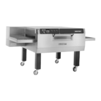
OPERATION
3 --- 1 0
NOTE: The switch is located in the front con-
trol compartment. It protects the other
components from hi ambient heat.
If this switch is cold, it should be made be-
tween common and N.C. terminals sending
power to the single solenoid gas valve (10).
4. When power is applied to the coils of both mo-
tor contactors (4) the contacts close sending
power t o the four convection fans (5) located
in the back of the oven. Power is also applied
to the coil of the SPST relay (3).
NOTE: The SPST relay acts as a hood inter-
lock and is sometimes used as a
means of starting the hood.
5. The oven has six cooling fans (19). Two on t he
front control panel keep the panel below 140_F
(60_C). The fan’s airflow is from left to right for
flow through ventilation. The other four, in the
rear of the oven, keep the convection fans from
overheating. The cooling fans start when the
motor contactor powers up and closes be-
tween terminals #5 and #6. Power goes to the
N.C. terminal of a SPDT thermal switch (18).
The sw itch toggles if the temperature passing
its face exceeds the rating on the back of the
switch and may start the fans even if the oven
is off. If this switch is cold, it should be made
between common and N.C. terminals sending
power to the cooling fans.
NOTE: The switch is located on the ceiling of
the convection fan compartment.
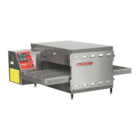
6. The conveyor is driven by an open loop D.C.
control s ystem consisting of a conveyor switch
(23), time display (26), potentiometer (24),
D.C. speed control board (28), 180 VDC motor
(27) and #10 Hall effect pickup (25). Refer to
page 5 ---1 for pickup troubleshooting. After the
conveyor switch is turned on, the time display
illuminates. The D.C. control board powers up.
The output voltage measured on the A1 and A2
of the board to the motor varies from 20 to180
VDC based on the position of the potentiome-
ter. The speed of the motor should also vary.
The time display varies depending on the
speed of the Hall effect pickup. The pickup
sends an R.P.M value to the display. The dis-
play converts this value t o minutes:seconds.
NOTE: This type of system does not sense the
weight of the product and will slow
down slightly if the belt is fully loaded.
7. If the thermal switch (9) in the control panel
toggles due to high heat, the single s olenoid
valve (10) closes. Power runs through a mo-
mentary switch (20) to the coil of a 240 volt
relay (21). When this relay closes, a buzzer (22)
sounds and an indicator lamp (29) lights, indi-
cating a control compartment high t empera-
ture. Pressing the momentary switch disen -
gages the relay, silencing the buzzer. The
indicator lamp remains lit until the temperature
drops 20_F across the face of the thermal
switch, allowing the burner to refire.
 Loading...