TECHNICAL APPENDIX
6 --- 2
SERVICE PROCEDURES
Service the IID system as follows:
1. Make certain the thermostat contacts are
open.
2. Check for proper supply voltage at primary
and secondary of system transformer.
3. Close thermostat contacts and observe sys-
tem.
4. Determine which system condition exists:
A.) No spark, system does not function
B.) Spark present but pilot will not light
C.) Pilot lights but main valve will not open
5. Follow the appropriate service checkout pro-
cedure to troubleshoot and repair the system.
6. Observe the system through s everal complete
operating cycles.
VOLTAGE AND CURRENT MEASUREMENTS
When servicing the electronic ignition control there
are several times w hen voltages and currents must
be measured or observed.
NOTE: All voltages measured will be AC voltage
and all current measured will be DC cur -
rent.
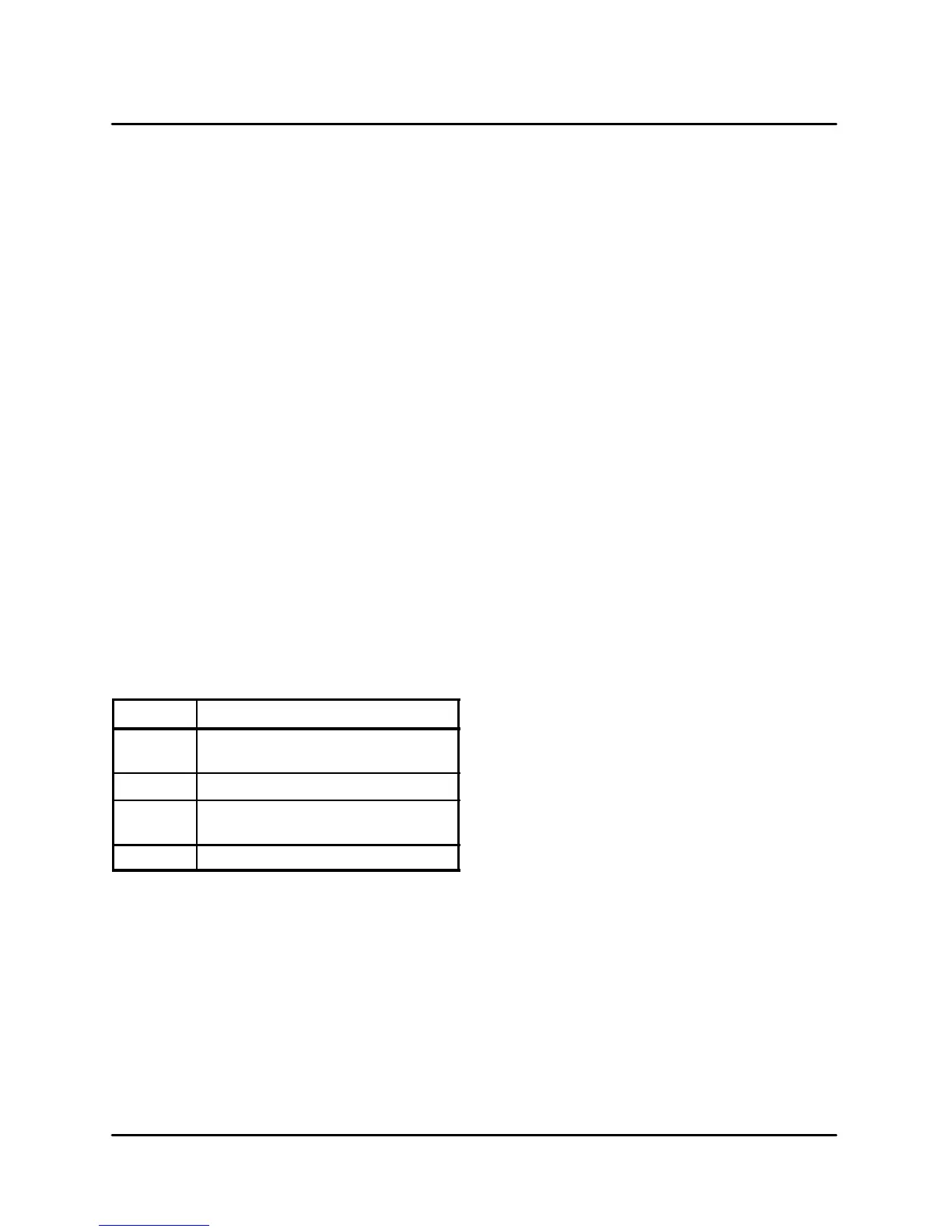
Te r m i na l
Te r m i na l Us e
1 Pilot valve connection between ter-
minal #1 and ground
2 Wire from thermostat
3 Main valve connection between ter-
minal #3 and ground
4 Flame sensor
TABLE 1
To M e a s u r e A C Vo l ta g e s :
1. Set the selector switch on the voltmeter to the
AC voltage position.
2. Connect the meter leads in parallel with the
voltagetobemeasured.
3. Read the voltage at the meter.
To Measure DC Flame Sensing Current:
1. Turn off t he power supply to the ignition con-
trol.
2. Disconnect the flame sensor cable from termi-
nal #4 on Johnson units or terminal #15 on
Landis & Gyr units.
3. Set the selector switch on the meter t o micro-
amp scale. Connect the positive (red) lead to
terminal #4 and the negative (black) lead t o
thesensorcable.
4. Disconnect the main valve lead from terminal
#3. This will prevent the main burner from ignit-
ing. A proper measurement of flame sensing
current is taken with the pilot light only.
5. Turn the power back on and close the thermo-
stat contacts. Read the current at the meter.
NOTE: The minimum current required for the
Johnson G770 is 0.15DCμA. The mini -
mum current required for the Landis &
Gyr is 2.0DCμA. (This unit is polarity
specific.)
6. Turn the power off to disconnect the meter and
reconnect terminal #3 and #4.
To Measure DC Flame Sensing Current Using
the Johnson Y99AU-3 Signal Transducer:
1. Set the function selector switch to the DC volt-
age position.
2. Turn off the supply voltage to the control.
3. Disconnect the flame sensor cable from termi-
nal #4 on the ignition control.
4. Connect the male 1/4” spade connector (---) to
the flame sensor cable. Connect the female
1/4” spade connector (+) to terminal #4.
5. Disconnect the main valve lead from terminal
#3 on the ignition control.
6. Turn the supply voltage on and close the ther-
mostat contacts to cycle t he system.
7. When the pilot lights, read the current on the
meter display.
NOTE: The conversion factor is 1DC volt --- 1
DC microamp.


 To Next Page