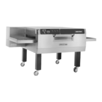
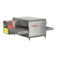
MT3255 and MT3270
3 --- 1 5
MT3270 WITH CLOSED LOOP --- M4206 REV B
NOTE: The following is also applicable to the
MT3255 with 3 blower motors.
COMPONENT REFERENCE
NOTE: Refer to FIGURE 10 page 3 ---25 for compo-
nent locations.
1. BLOWER SWITCH (M0153)
2. TEMPERATURE CONTROL (M3149)
3. MOTOR CONTACTORS A & B (M0708)
4. HI/LO LIMIT BOARD (M 3150)
5. CONVECTION FANS (Clockwise --- M 4224,
Counter-clockwise --- M4225)
6. THERMOCOUPLES (Dual lead --- M3151,
Single --- M3152)
7. HEAT SWITCH (M0152)
8. COMBUSTION MOTOR (22132)
9. PRESSURE SWITCH (M0595)
10. 115/24 TRANSFORMER (M2381)
11. PURGE RELAY (M2382)
12. CENTRIFUGAL SWITCH
13. IGNITION CONTROL MODULE (M1054)
14. PILOT VALVE (LP --- 22190, Natural --- M5495)
15. MAIN VALVE (LP --- 22190, Natural --- M5495)
16. SPST THERMAL SWITCH (M1362)
17. SINGLE SOLENOID GAS VALVE (20287)
18. COOLING FANS (4-1/2” --- M2469,
3-1/5” --- 21134)
19. SPDT THERM AL SWITCH (M2453)
20. CONVEYOR SWITCH (M0152)
21. D.C. MOTOR (M2378)
22. TIME DISPLAY/MOTOR DRIVE (M3393)
23. #2 HALL EFFECT PICKUP (M0984)
OPERATION
1. Turn the blower switch (1) to ON. The N.O. con-
tacts close, the N.C. contacts open. 115 VAC
runs to terminal #1 of the temperature control-
ler (2), both coils of the motor contactors (3)
and terminal #7 of the hi/lo limit board (4). Ter-
minal #7 is a n output. It remains powered after
the oven is shut down to keep the convection
fans (5) operating until the unit reaches
135---170_F (57---77_C) as sensed by the ther-
mocouples (6).
NOTE: Two thermocouples are located be-
tween the middle convection fans in
the rear of the oven. One thermocouple
provides DC millivolts to the Hi/Lo limit
board. The other provides DC milivolts
to the temperature controller. Check
thermocouples with a millivolt meter.
2. Turn the heat switch (7) to ON. Power goes to
terminal #6 of the temperature controller (2)
and terminal #5 of the Hi/Lo limit board (4). A
circuit is made between terminals #5 and #6
of the Hi/Lo limit board. This switch opens if the
oven cavity temperature exceeds 600_F
(316_C) as sensed by the thermocouples. Ter-
minal #6 of the Hi/Lo board is an output and
sends power to a pressure s witch (9). The
switch reacts from a vacuum created by t he
convection fans. I f the switch is closed, power
runs to the primary side of a 115/24 VAC tra ns-
former (10) and a contact on the purge relay
(11).
NOTE: These components are located in a
box mounted on top of the combustion
motor.
When24VACisappliedtothisrelay,thecon-
tacts close sending 115 VAC to start the com -
bustion motor (8). When the combustion mo-
tor reaches full speed, a centrifugal switch (12)
closes sending 24 VAC to the ignition module
(13). After the module’s self diagnostics are
complete, the pilot valve (14) opens. When a
proof of flame is established, the main burner
valve (15) opens.
3. Output from the temperature controller (2)
goes from terminal #4 to a terminal of a SPST
thermal switch (16). The switch toggles if the
temperature passing its face exceeds t he rat-
ing on the back of the switch.
 Loading...