MT3255 and MT3270
6 --- 1
INTERMITTENT IGNITION SYSTEM
PRINCIPLES OF OPERATION
Pilot flame sensing is a very important aspect of the
ignition controls operation. Three zones are need-
ed to give the proper air-gas ratio to produce a blue
pilot flame.
Zone 1 --- an inner cone t hat w ill not burn because
excess fuel is present.
Zone 2 --- around the inner, fuel rich cone is a blue
envelope. This zone contains a mixture of vapor
from the fuel rich inner cone and the secondary or
surrounding air. This is where combustion occurs,
and is the area of highest importance for proper
flamesensorlocation.
Zone 3 --- Outside the blue envelope is third zone
that contains an excessive quantity of air.
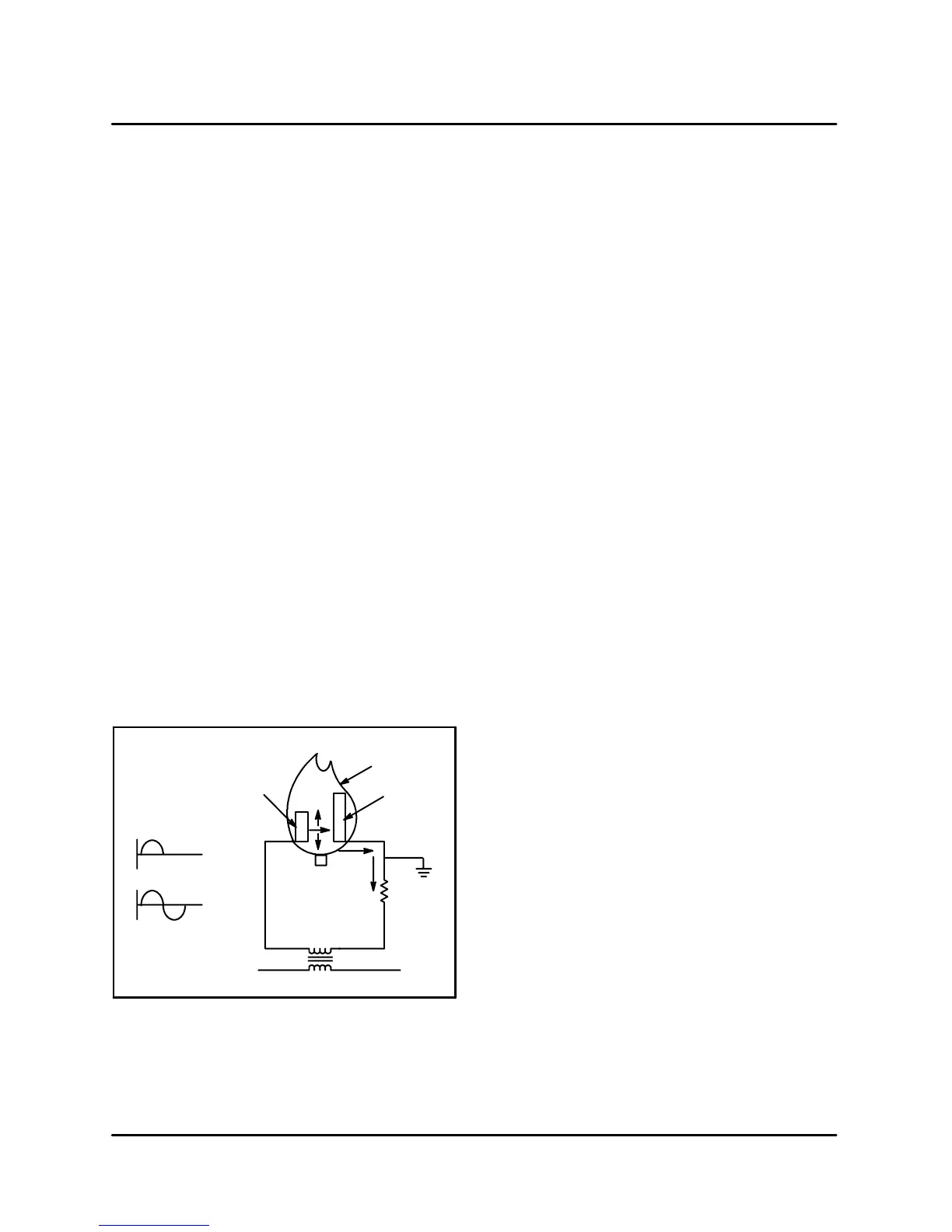
FLAME RECTIFICATION
To identify a current conducted by the flame, we
use flame rectification. Place two probes in Zone 2
of the pilot flame. When the surface area of one
probe is larger than the other, current tends to flow
more in one direction. DC current flows in only one
direction, as opposed to AC current, which alter-
nates its direction. The current is rectified from AC
to DC by increasing the surface area of one probe
and decreasing the surface area of t he other.
+ ---
AC Voltage
Transformer
Ground
DC
Current
DC
Current
Flame
Negative
Probe
Positive
Probe
+
DC
Current
+
AC
Voltage
---
FIGURE 1
In the IID system the probes exposed to the pilot
flame are the Flame Sensor and the Pilot B urner
Hood. Since the surface area of the pilot hood is
larger than the flame sensor, the current rectifica-
tion process tak es place. Current is conducted
from terminal 4 at the control t hrough the flame
sensor cable to the flame sensor. As the current is
conducted through the flame to the pilot hood, it is
rectified from AC to DC because of the difference
in surface area. The pilot hood is grounded back
to the control, thereby completing the circuit.
Flame Sensing Circuit Current
For the ignition control to function properly, a mini-
mum amount of current must flow through t he
flame sensing circuit.
As the pilot flame is established and current begins
to flow in the flame sensing circuit, the current en-
ergizes a relay. A minimum amount of current is re-
quired to pull-in the relay. When the relay pulls in,
one set of contacts opens which shuts off the high
energy spark . Another set of contacts closes, putt-
ing 24 volts on terminal 3 which opens the main
gas valve.
Current vs. Voltage
In normal operation an AC voltage w ill be present
from terminal 4 to ground and a current w ill be
present in the flame sensing circuit.
Even though an AC voltage is present, flame rectifi-
cation occurs and a DC current flows in the sensing
circuit.
For service check out purposes, measuring these
voltages and currents can provide useful informa -
tion regarding the integrity of the ignition control.
Measuring the current flow rather than voltage is
the preferred procedure. D ue to the internal circuit-
ry of the ignition control and varying input imped-
ance of voltmeters, the measured voltage will vary
depending on type and model of voltmeter being
used. However, measuring the current provides a
more precise evaluation of the ignition control and
flame sensing circuit.
A proper reading not only indicates a functional
control, but also verifies all components of the cir-
cuit such as flame sensor, ca ble and ground.
 Loading...