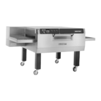
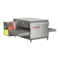
OPERATION
3 --- 2 0
er times out, power goes to the coil of a SPST
relay (14), allowing its contacts to close.
4. On a call for heat from the temperature control-
ler (2), as sensed by the thermocouples, a set
of contacts closes sending power out of termi-
nal #4 of the temperature controller to the
common t erminal of the SPDT thermal switch
(15). The switch toggles if the temperature
passing its face exceeds the rating on the back
of the switch.
NOTE: The switch is located in the front con-
trol compartment. It protects the other
components from hi ambient heat.
If this switch is cold, it should be made be-
tween common and N.C. terminals sending
power to one side of the SPST relay (14). This
relay was closed shortly after the 10 second
purge timer (13) timed out. Power is sent to ter-
minal #1 of the Landis and Gyr ignition control
system (16). Terminal #8 of the ignition control
module is an output. It sends power to a 2 sec-
ond p urge timer (17) and the pilot valve (18).
The main valve (19) opens when t he 2 second
purge timer times out. If the ignition control
senses a flame the system remains energized.
If not, the control locks out within 1 to 3 sec-
onds. The ignition alarm light (20) illuminates.
NOTE: Thissystemispolarityspecific.Ifthe
unit locks out repeatedly and the D.C.
microamps are within the acceptable
range, check for proper polarity.
5. When power is applied to the coils of both mo-
tor contactors (3) the contacts close sending
power t o the four convection fans (6) located
in the back of the oven. Power is also applied
to the coil of the SPST relay (4).
NOTE: The SPST relay acts as a hood inter-
lock and is sometimes used as a
means of starting the hood.
6. The oven has six cooling fans (21). Two on t he
front control panel keep the panel below 140_F
(60_C). The fan’s airflow is from left to right for
flow through ventilation. The other four, in the
rear of the oven, keep the convection fans from
overheating. The cooling fans start when the
motor contactor powers up and closes be-
tween terminals #3 and #4. Power goes to the
N.C. terminal of a SPDT thermal switch (22).
The sw itch toggles if the temperature passing
its face exceeds the rating on the back of the
switch and may start the fans even if the oven
is off. If this switch is cold, it should be made
between common and N.C. terminals sending
power to the cooling fans.
NOTE: The switch is located on the ceiling of
the convection fan compartment.
7. The conveyor is driven by an open loop D.C.
control s ystem consisting of a conveyor switch
(23), time display (24), 10kΩ potentiometer
(25), D.C. speed control board (26), 180 VDC
motor (27) and #10 Hall effect pickup (28). Re-
fer to page 5 ---1 for pickup troubleshooting. Af-
ter the conveyor switch is turned on, the time
display illuminates. The D.C. control board
powers up. The output voltage measured on
terminals A 1 and A2 of the board to the motor
varies from 20 to180 VDC based on the posi-
tion of the potentiometer. The speed of the mo-
tor s hould also vary. The time display varies de-
pending on the speed of the Hall effect pickup.
The pickup sends an R.P.M value to the dis-
play. The display converts this value to min-
utes:seconds.
NOTE: This type of system does not sense the
weight of the product and will slow
down slightly if the belt is fully loaded.
8. If the thermal sw itch (15) in the control panel
toggles due to high heat power is interrupted
to the ignition control system. Power runs
through a momentary switch (29) to the coil of
a 220 or 240 volt relay (32). When this relay
closes, a buzzer (30) sounds and an indicator
lamp (31) lights, indicating a control compart-
ment high temperature. Pressing the momen-
tary switch disengages the relay, silencing the
buzzer. The indicator lamp remains lit until the
temperature drops 20_F(11_C) across the
face of the thermal switch, allowing the burner
to refire.
 Loading...