Blue Box - 34
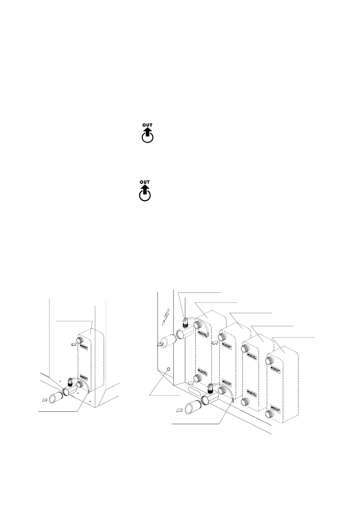
4.8 WATER FLOW SWITCH INSTALLATION INSTRUCTIONS
(supplied as a kit for each evaporator)
- Clean the piping system into which the flow switch is to be fitted and remove any magnetic particles, such as
welding residues etc.
- To prevent turbulent flow there must be straight pipework, equal to 5 times the diameter of the pipe, either side
of the flow switch.
" Connect the "T" shaped metallic manifold (on which the flow switch is mounted) into the evaporator male
threaded water outlet labelled with:
Figure 9
For HEAT PUMP units, repeat the operation and screw the "T" shaped brass manifold (on which the second flow
switch is mounted) into the condenser male threaded water outlet labelled with:
To avoid leakage, seal the connection by using teflon. The flow switch should be installed on the heat exchanger
that is closer to the electrical board.
Heat exchanger
Connect to
terminal box
Heat pump version
only
Heat exchanger
(condenser)
Heat exchanger
(evaporator)
Hole for
electrical cable
Connect to terminal box
Heat exchanger
(condenser)
Heat exchanger
(evaporator)
CONDENSER WATER
EVAPORATOR WATER