Blue Box - 35
Warning: When connecting or fabricating pipework never work with naked
flames either inside the unit or in the immediate vicinity of the unit.
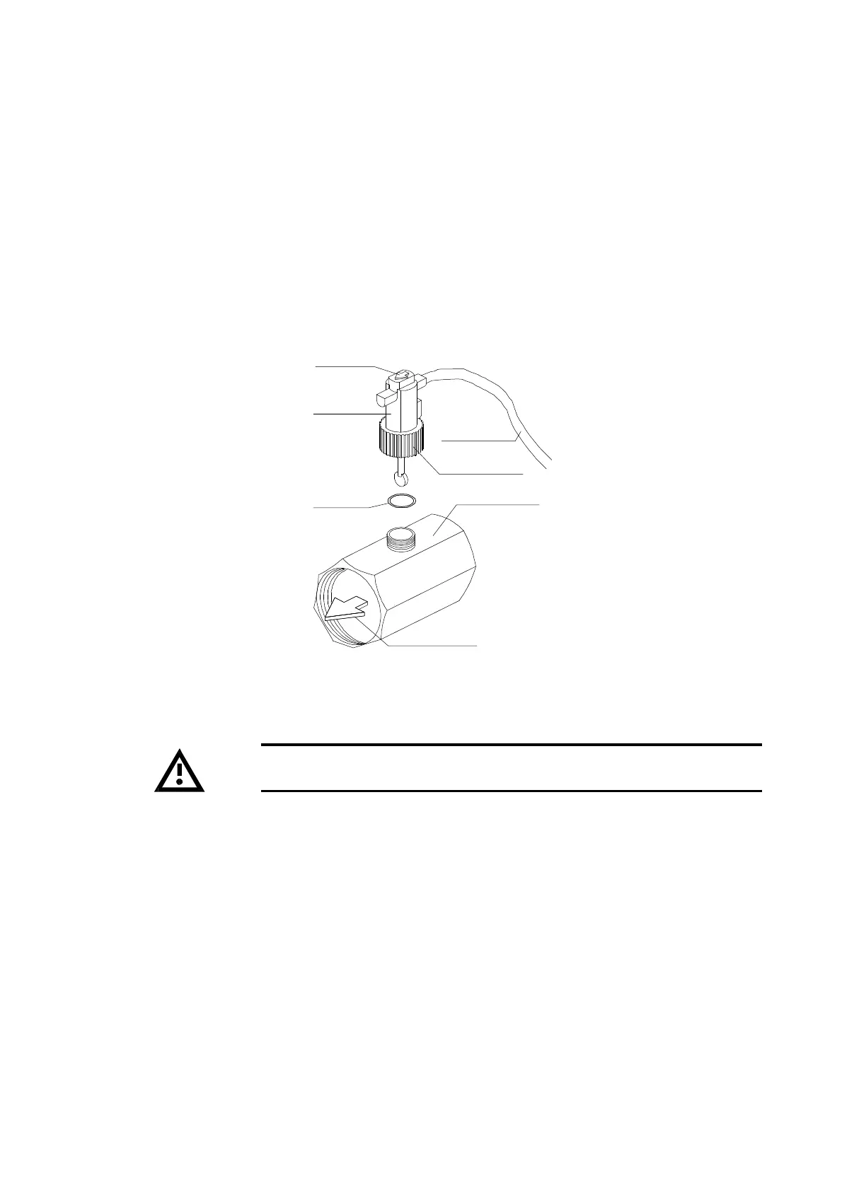
- The flow switch must be tightened on the “T” shaped metallic manifold by the plastic knurled union nut. Check
that the arrow located on the upper side is pointing in the direction of flow.
- Be sure to fit the O-ring seal, through the brass manifold and the plastic ring nut. The O-ring seal is supplied in
a plastic cover to protect the flow switch shaft.
- Connect the flow switch to the other end of the “T” manifold.
- Route the flow switch electrical cable through the hole in the unit structure and run it to the electrical panel by
ascending the upright in the machine interior. Connect the flow switch to terminals 1-14 as indicated on the
electrical drawing.
- The flow switch can be removed by screwing out the plastic knurled union nut. In order to reassemble it, ensure
that the o-ring seal is positioned in the proper location. (See figure10).
Figure 10
Arrow
Flow switch
O Ring
Electric cable
Plastic union nut
“T” shaped brass manifold
Flow direction