GENERAL MAINTENANCE
38
EVERY 40 HOURS OF OPERATION
Note: Escaping hydraulic fluid, under pressure, can be dangerous. Hydraulic fluid
escaping under pressure can have enough force to penetrate the skin or destroy
eye-sight. Hydraulic fluid may also infect a minor cut or opening in the skin. If
injured by hydraulic fluid, seek medical attention at once. Make sure all connections
are tight and that hoses are in good condition before applying pressure to system.
Relieve all pressure to system (Stop Engine) before disconnecting lines or
attempting to perform other work on the system. To locate small leaks, use a small
piece of cardboard, paper, or wood … never use your hands.
B.
Physically check all pins, cotter pins, nuts, etc. for signs of wear or loose fit. Tighten as required, replacing where
necessary. (Bolts, pins, may vibrate loose during operation). Clean equipment of all dirt, oil, and excess grease.
This will assist you in making usual inspections and help avoid dangerous slips.
EVERY 200 HOURS OF OPERATION
Hydraulic oil should be drained out of system and replaced with clean Fluid per filling instructions.
Pressure relief valve operation should be checked to assure operation at designated level.
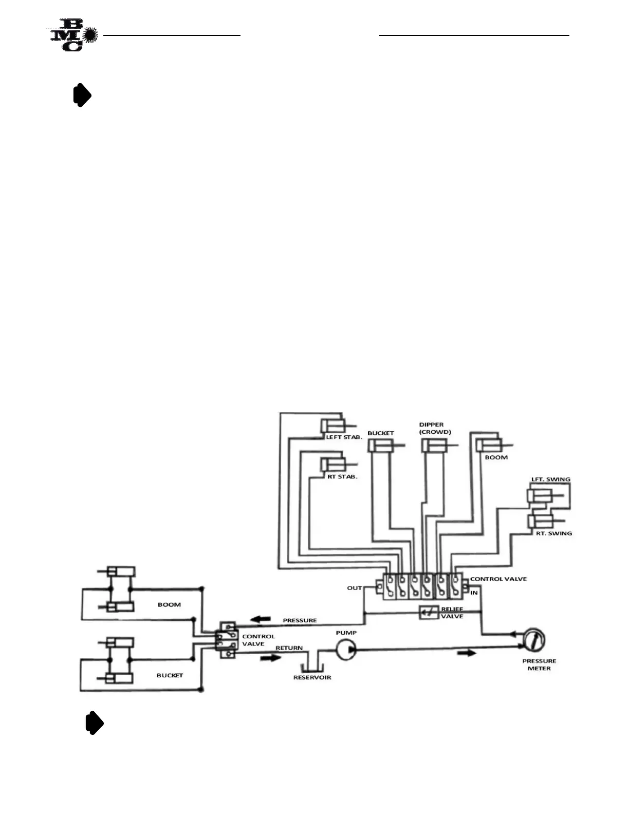
To check pressure an “in-line” type pressure meter (not “end-of-line) should be used. Fig. 1 below is a line
drawing indicating proper connection for checking pressure on both backhoe and loader. (Always stop tractor engine
prior to making any hydraulic connections). Once the meter is properly connected into the fluid circuit, “bottom” out
any cylinder on the backhoe. As cylinder moves, pressure will rise and will level off as relief valve (located in input
section of control valve) opens. This leveling off should occur at 1800 P.S.I. (1750–1850). Reverse the handle
movement, moving cylinder in opposite direction so that cylinder is no longer “bottomed” and then release handle so
it can return to center position. Should it be necessary to adjust relief valves this is accomplished with a screwdriver
adjustment of spring tension inside acorn nut cover on relief valve. Turning screw to right raises pressure; to left
lowers pressure. Each turn of this screw will change relief valve operation pressure point by approximately 700 P.S.I.
FIG. 1
DO NOT SET RELIEF VALVE OPERATING PRESSURE HIGHER THAN THAT LEVEL SPECIFIED ABOVE. THE
RELIEF VALVE IS THERE TO PROTECT YOUR EQUIPMENT AND YOUR PERSONAL SAFETY. DAMAGE DONE
DUE TO TOO HIGH PRESSURE IS NOT COVERED BY PRODUCT WARRANTY. IT IS YOUR RESPONSIBILITY, AS
THE OWNER OR OPERATOR, TO MAINTAIN PROPER FLUID LEVELS AND PROPER PRESSURE SETTINGS.