LD6 AND MD8 HOSE INSTALLATION
22
The control valve and hoses for the BMC Series LD6
and MD8 Backhoe are shipped loose, in hose kit carton
except for the swing cross-over hoses which are
installed. The hosing of the LD6 and MD8 Backhoe are
identical except the length of the hoses and physical
location of the hydraulic ports on the crowd cylinders
and bucket cylinders. The photos used for illustration
are mixed. To prevent chafing of the hydraulic hoses
the following instructions must be followed:
(1) Mount Control Valve (Item 1) to the inside front
plate of the mainframe as oriented in Fig. 2. Secure
with (2) each 3/8” x 1” machine bolts, lockwashers and
hex nuts provided.
(2) Complete installation of the stabilizer handles
by aligning the hole in the right stabilizer handle with
the hole in the control valve spool. Insert a 5/32” x
13/16” pin and secure the pin with ¼” clip.
(3) Repeat step two (2) for left stabilizer handle.
Fig. 2
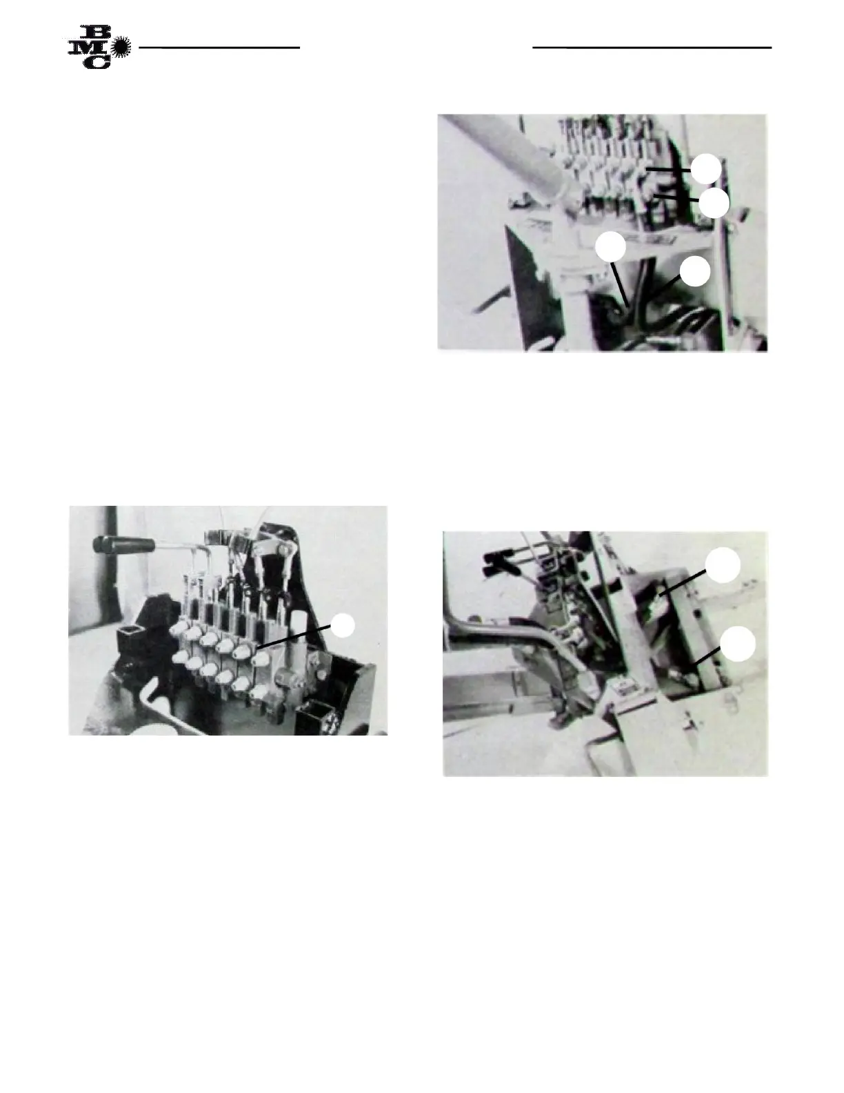
(4) Connect end of “Left Swing” hose (Item 2)
equipped with short 90° fitting to lower port (Point C1)
on far right hand section of control valve as shown in
Fig. 3. Route through opening in the lower inside front
plate on left side of main frame and connect to the top
front port (Point C2) on the left swing cylinder as shown
in Fig. 4.
Fig. 3
(5) Connect end of “Right Swing” hose (Item 3)
equipped with long 90° fitting to upper port (Point D1)
on far right hand section of control valve as shown in
Fig. 2. Route through opening in the lower inside front
plate on right side of mainframe and connect to the top
front port (Point D2) of the right swing cylinder as
shown in Fig. 4.
Fig. 4
(6) Connect end of “boom up” hose (Item 4) equipped
with short 90° fitting to lower port (Point E1) on second
valve section from right as shown in Fig. 5. Route hose
through hole in top plate of mainframe (located just
behind swing shaft) and connect to fitting located on
top of load check (Point E2) mounted in the top port of
main boom cylinder as shown in Fig. 6. Using a plastic
hose tie (Item 8) in box parts) fasten the hose to the
boom cylinder approximately 1” to 2” behind the lower
hydraulic port.
1
1
2
D1
C1
3
C2
D2