LD6 AND MD8 HOSE INSTALLATION
23
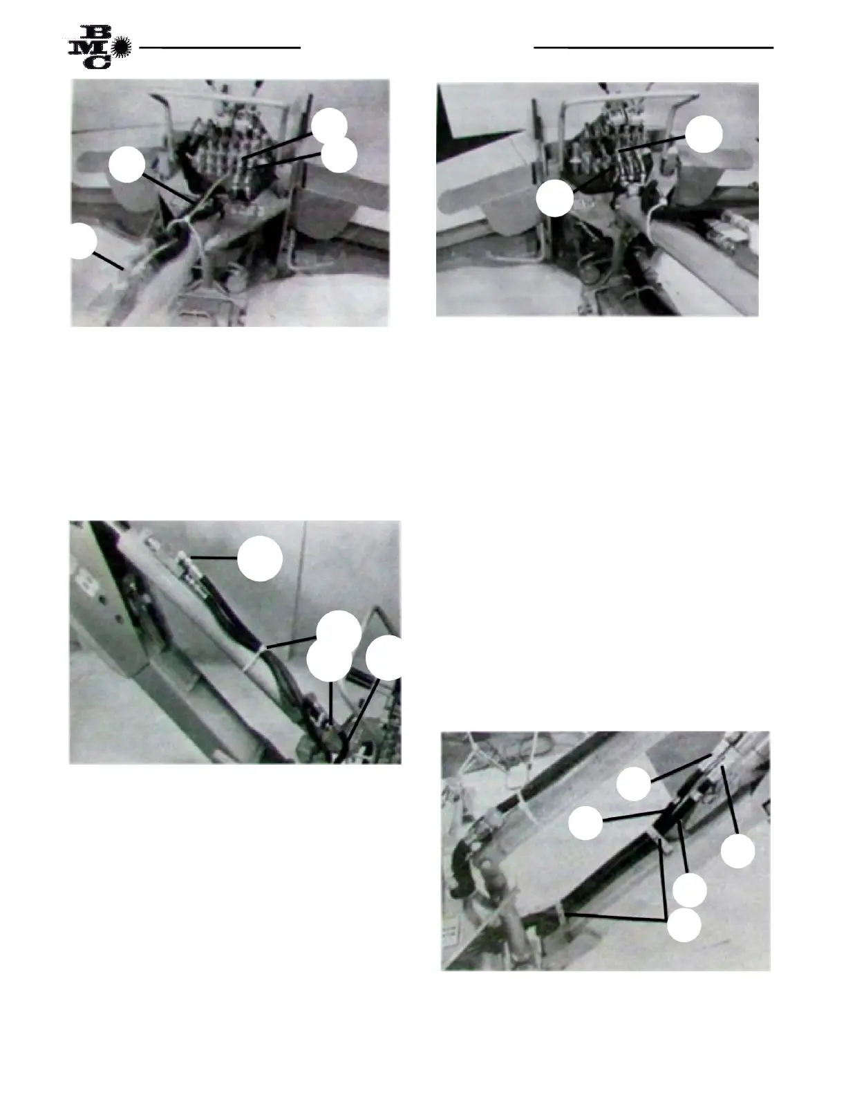
Fig. 5
(7) Connect end of “boom down” hose (item 5)
equipped with long 90° fitting to upper port (Point F1)
on second valve section from right as shown in Fig. 5.
Route hose through hole in top plate of mainframe and
connect to the open end of Tee Adaptor on lower main
boom cylinder port (Point F2) as shown in Fig. 6.
Fig. 6
(8) Connect end of “dipper close” hose (Item 6)
equipped with short 90° fitting to lower port (Point F1)
on third valve section from right as shown in Fig. 7.
Route past lower swing shaft on the right side, over the
hose guard, along top of main boom and connect to the
cylinder port on the base end of the crown cylinder
(Point G2) as shown in Fig. 8.
Fig. 7
(9) Connect end of “dipper open” hose (Item 7)
equipped with long 90° fitting to upper port (Point H1)
on third valve section from right as shown in Fig. 7.
Route past lower swing shaft on the right side, over
hose guard, along top of boom and connect to the
cylinder port on rod end (Point H2) as shown in Fig. 8.
(10) Using one (1) each plastic hose tie, (Item 8 in
box parts list), fasten the dipper open hose to the crowd
cylinder at mid-point. Pull all the slack in the two crowd
hoses toward the swing shaft and secure to the boom
(loosely) with two (2) each hose clamps (Item 11 in
boom assembly) and two (2) each ¼” x 1 ¼”bolts. The
dipper open hose (connected at Point H1 and H2) must
lay to the inside of the swing shaft and hose clamps.
The dipper close hose (connected at Point G1 and G2)
must lay to the outside of the swing shaft and hose
clamps. See Fig. 7 and 8.
Fig. 8
E1
F1
E2
4
G1
H1
E2
8
F2
5
G2
6
H2
7
11