LD6 AND MD8 HOSE INSTALLATION
24
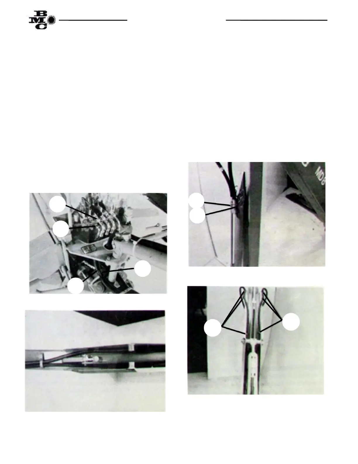
(11) Connect end of “bucket open” hose (Item 8)
equipped with short 90° fitting to the lower Port (Point
J1) on fourth valve section from right as shown in Fig.
9. Route hose past swing shaft on the left side, over
hose guard, under hose clamps on boom, crossing over
to the right side of the boom at the base end of the
crowd cylinder as shown in Fig. 10. Route hose on the
inside of the boom side plates and over the end of the
boom. Measure approximately 19” on LD6 and 37” on
MD8 from the loose end of the hose and secure at that
point using a 1” insulated hose clamp (Item 10 in box
parts) and 3/16” x ¾” machine screw, lockwasher and
nut. Connect the hose to the rod end Port (Point J2) of
the bucket cylinder as shown in Fig. 11. Complete
attaching the hose to the boom side plate using two (2)
other 1” insulated clamp as shown in Fig. 12. Using a
plastic hose tie (Item 8 in box parts) fasten the hose to
the bucket cylinder approximately 3” below the base
end Port.
Fig. 9
Fig. 10
(12) Connect end of “bucket close” hose (Item 9)
equipped with long 90° fitting to the upper Port (Point
K1) on the fourth valve section from right as shown in
Fig. 9. Route hose past swing shaft on the left side,
inside of the left boom side plates and over end of boom
measure approximately 38” on LD6 and 37” on MD8
from the loose end of the hose and secure at that point
using a 1” insulated hose clamp (Item 10 in box parts)
and 3/16” x ¾” machine screw, lockwasher and nut.
Connect the hose to the base end Port (Point K2) of the
bucket cylinder as shown in Fig. 11. Complete
attaching the hose to the boom side plate using
remaining two (2) 1” insulated hose clamps as shown in
Fig. 12.
Fig. 11
Fig. 12
K1
J1
9
8
10
10
J2
K2