MOUNTING INSTRUCTIONS
10
NOTE: (1) Right or left designations have reference to right or left side of tractor when seated
facing forward.
1 Remove 2” x 6” cross-pieces from shipping pad. Remove bolts holding 605 Backhoe to shipping
pad. (Located inside mainframe, about the center of the pad.)
2 Cut wire holding control handles into place, raise each one into place and insert pin, fastening with
C-ring provided. (Pins and C-ring are shipped inserted in appropriate holes.)
3 Stabilizers are shipped separately boxed. Mount right side stabilizer 601. (Note flange position on
assembly drawing. Turned-down portion of stabilizer plate faces forward.) Insert 667 pin and
fasten with cotter keys. Fasten stabilizer cylinder to mounting ear on backhoe mainframe using
604 pin and cotter pins. (Ref. Stabilizer Assembly Drawing, page 16, for details.) Connect short
hose (638) to top of cylinder and long hose (627) to bottom of cylinder. Repeat process for left side
stabilizer 602, connecting hoses 634 and 629 respectively to top and bottom of left cylinder. (See
Hose Assembly, page 20.)
4 Remove 713 extension arms from shipping pad. Slide right side 713 extension arm over top of 591
loader mainframe (Ref. 505 Loader Manual, page 11) and attach loosely, using ½ x 2 bolts
provided, to tractor mainframe. (Holes in tractor mainframe located just forward of loader 591
maincross frame.) Mount 713 left side extension in same manner.
5 Back HT-20 Tractor over extended short arms of 605 Backhoe until holes (C) are situated directly
under mounting ears on right and left side tractor axles. Use small jack (or manually) lift 605
Backhoe until holes (C) align with mounting ears on tractor axle (points D and H in Loader Manual,
page 7). Remove bolt in tractor mounting ears, raise backhoe until bolts can be re-inserted thru
hole (C) on backhoe. Do not tighten.
6 Tilt backhoe until notched end of 605 extended arms align with holes (B) in 713 extension arms.
Fasten loosely with 3/4 x 2 bolts provided. Also align notched end of 713 extension arms with lower
holes (A) in 605 mounting arms. Fasten with 3/4 x 2 bolts provided. Tighten all bolts (D), (B), (A)
and at point (C).
7 When used with Brantly 505 Front End Loader, pump assembly will already be mounted.
a. Remove 595 hose (supplied with loader) from pump output (point M) and loader control
valve input (point N).
b. Attach 677 hose to point M (pump output), passing hose down left side of tractor over 591
loader main crossframe, thru opening in lower right front panel on 605 Backhoes and connect
other end to point E (input on backhoe control valve; Ref. page 18,20).
c. Attach 676 hose to 505 loader valve input (point N), passing hose down right side of tractor,
thru opening in lower left panel on 605 Backhoe and connect other end to point F
(output of backhoe control valve; Ref. page 18,20).
NOTE:
8
If 505 loader is not used, then 675 pump assembly will
be required. Mount in accordance with instructions on
page 14, connect 676 hose to output of pump and to
point F on backhoe control valve.
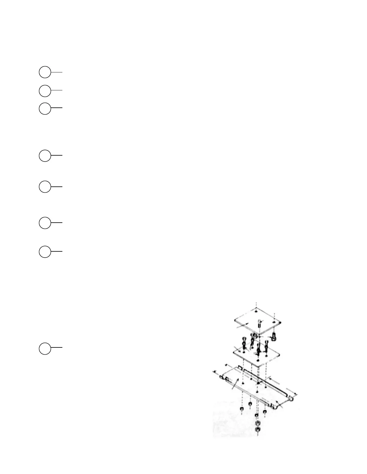
Mount seat swivel as follows: (1) Remove existing
seat bolts (C) holding seat to existing bracket (E).
Drill 1/2 inch hole, as shown, in existing bracket (E).
Mount seat swivel top plate (A) to bottom of seat
using bolts previously holding seat to existing
bracket. (NOTE: Bolt (F) should point downward).
Mount seat swivel lower plate using four bolts (D)
provided to existing seat bracket (E) as shown. Place
seat with top swivel plate over lower swivel plate.
Insert bolt (F) thru hole in lower swivel plate and
thru hole drilled in bracket (E). Fasten with two
5/16” nuts provided so that seat swivels easily, but
does not wobble.
EXISTING
SEAT BRACKET
DRILL ½” HOLE
4 1/8
A
B
C
D
E
6”
F
 Loading...