Vehicle Interface of Integrated Communication Optical Module (ICOM)
Page 23
User Guide
of 29
Copyright © BMW AG / ICOM User Guide
Version 1.0/ Februar 08
5.
Wearing Parts
5.1
Replacement of ICOM A (connector module)
The OBD II module is to be replaced in the corresponding order, complying with the following
work steps and safety instructions:
All work is only to be carried out when the device voltage is not applied. It is only
permitted to use standardized screwdrivers and spanners that are exclusively intended
for this purpose and where the size of the tool matches the screw / bolt head to work on
bolt / screw connections.
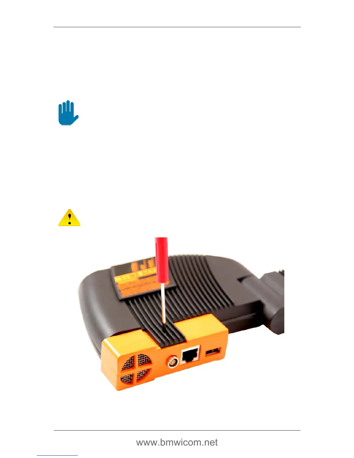
1. Remove the screw on the back of the ICOM A (see Fig. 16)
2. Turn the ICOM A around and pull out the orange LAN module straight upwards
(see Fig. 17)
3. Snap the new LAN module into place in the guide rails
4. Reinsert the screw on the back of the ICOM A and tighten it
(see Fig. 18)
It must be ensured that the screw is NOT tightened excessively!
Fig. 16 Removing / tightening the retaining screw
 Loading...