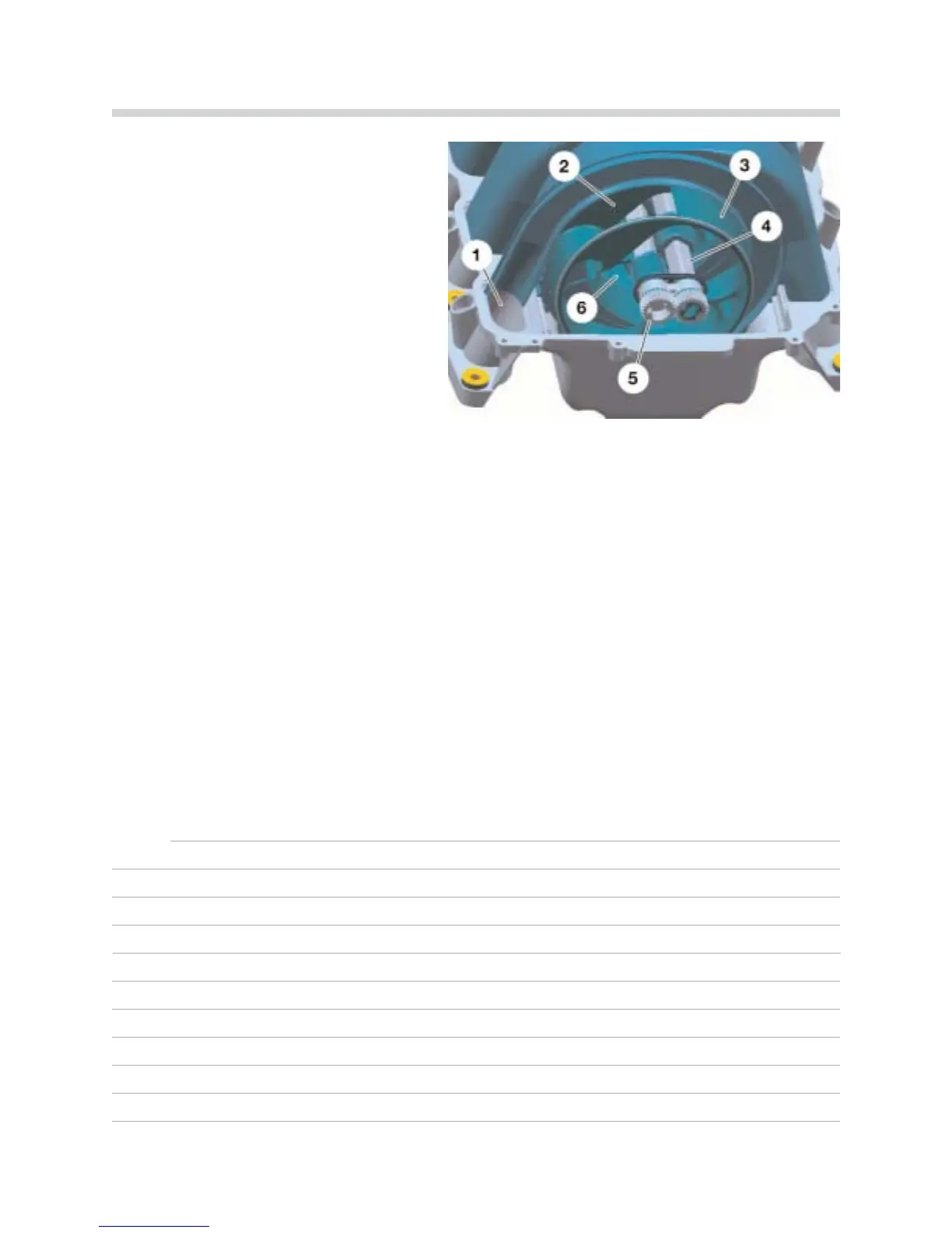
Each cylinder has its own intake pipe (1) which is connected to the manifold volume (6) via
a rotor (3). The rotors are supported by one shaft (4) per cylinder bank.
The second shaft, from which the rotor for the opposite cylinder bank is adjusted, is turned
by spur gears (5) in the opposite direction from the driven shaft.
The intake air flows via the manifold volume through the funnel (2) and on to the cylinders.
The intake path length is set as the rotor turns.
The intake path length can be adjusted according to the engine speed. Adjustment from
the long to short intake path begins at 3,500 rpm. If the engine speed increases, the intake
path length is progressively reduced, up to 6,200 rpm.
NNootteess::
10
N62 Engine
42-02-09
The Variable Intake Manifold
1. Intake Port
2. Funnel
3. Rotor
4. Shaft
5. Spur Gears
6. Manifold Volume
 Loading...