BOGE Operating instructions for scroll compressors, series EO 6...EO 22 D Page 81
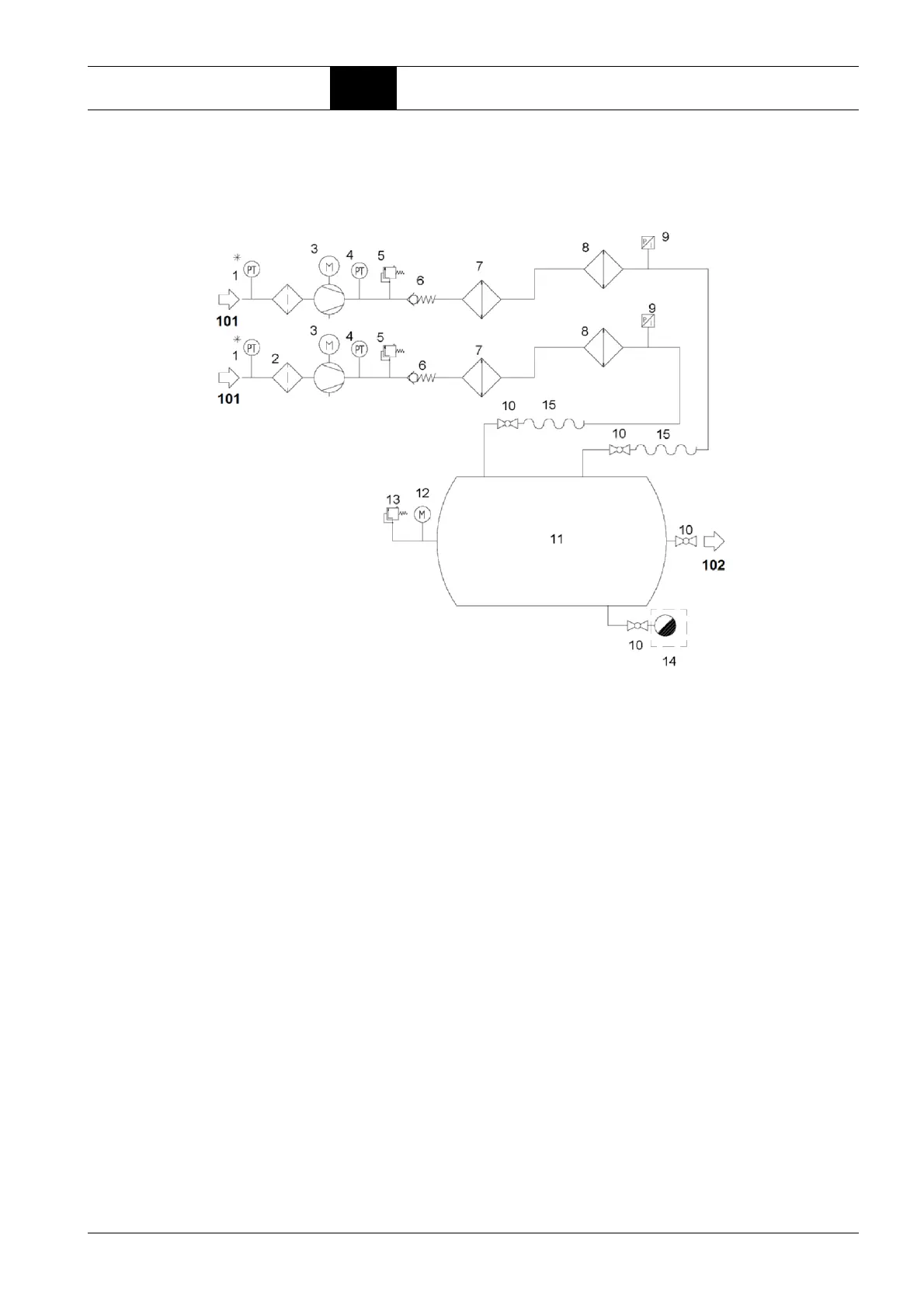
Appendix 8.3 Pneumatic circuit diagrams
Pneumatic circuit
diagram for EO 6 TR,
air-cooled
101 Intake air INLET
102 Compressed air OUTLET
1 Intake air temperature *
2 Suction filter
3Unit
4 Final compression temperature
5Safety valve
6 Non-return valve
7 Primary cooler
8 Secondary cooler
9 Net pressure
10 Ball valve
11 Receiver
12 Pressure indicator
13 Receiver safety valve
14 Receiver condensate drain (option)
15 Hose
* with focus control 2.0
 Loading...