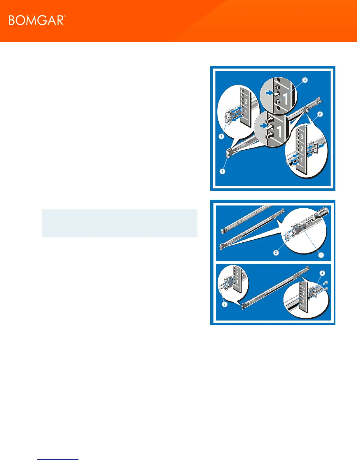
2. Installing and Removing Tool-less Rails (Square Hole or Round
Hole Racks)
Position the left and right rail end pieces labeled FRONT facing
inward and orient each end piece to seat in the holes on the front
side of the vertical rack flanges (1).
Align each end piece in the bottom and top holes of the desired U
spaces (2).
Engage the back end of the rail until it fully seats on the vertical
rack flange and the latch clicks into place. Repeat these steps to
position and seat the front end piece on the vertical rack flange (3).
To remove the rails, pull the latch release button on the end piece
midpoint and unseat each rail (4).
3. Installing and Removing Tooled Rails (Threaded Hole Racks)
Note: The tooled rail mounting configuration requires eight
user-supplied screws: #10-32, #12-24, #M5, or #M6. The
head diameter of the screws must be less than 10 mm (0.4”).
Remove the pins from the front and rear mounting brackets using a
flat-tipped screwdriver (1).
Pull and rotate the rail latch sub-assemblies to remove them from
the mounting brackets (2).
Attach the left and right mounting rails to the front vertical rack
flanges using two pairs of screws (3).
Slide the left and right back brackets forward against the rear
vertical rack flanges and attach them using two pairs of screws (4).
CONTACT BOMGAR info@bomgar.com | 866.205.3650 (US) | +44 (0) 1628 480 210 (UK/EMEA) BOMGAR.COM 11
© 2017 Bomgar Corporation. All rights reserved worldwide. BOMGAR and the BOMGAR logo are trademarks of Bomgar Corporation; other trademarks shown are the property of their respective owners. TC: 1/11/2018
REMOTE SUPPORT APPLIANCE INSTALLATION