Theory of Operation Section 4
4-1
SECTION IV
THEORY OF OPERATION
4-1. INTRODUCTION.
4-2. The Model 1121A is a versatile, solid-state, micro-
processor controlled, audio analyzer that covers the
frequency range of 10 Hz to 140 kHz. The instrument
contains an independent audio source and analyzer for
stimulus response testing with simultaneous display of
source settings and analyzer measurements. Function
parameters can be keyed in through a front panel key-
board or with remote programming using the IEEE-488
interface. Selected modes and values are displayed on
an alphanumeric display and LED indicators. Input com-
mands are processed by the internal microprocessor and
control signals are developed to configure the internal
circuits in accordance with the commands. The use of the
microprocessor also enables the storage of up to 99
complete sets of instrument setup data. Commonly used
setups can be entered into non-volatile memory either
through the keyboard or through the IEEE-488 interface;
thereafter, the instrument can be set to any desired set of
conditions in memory by keying in the code number
assigned to the desired setup in storage.
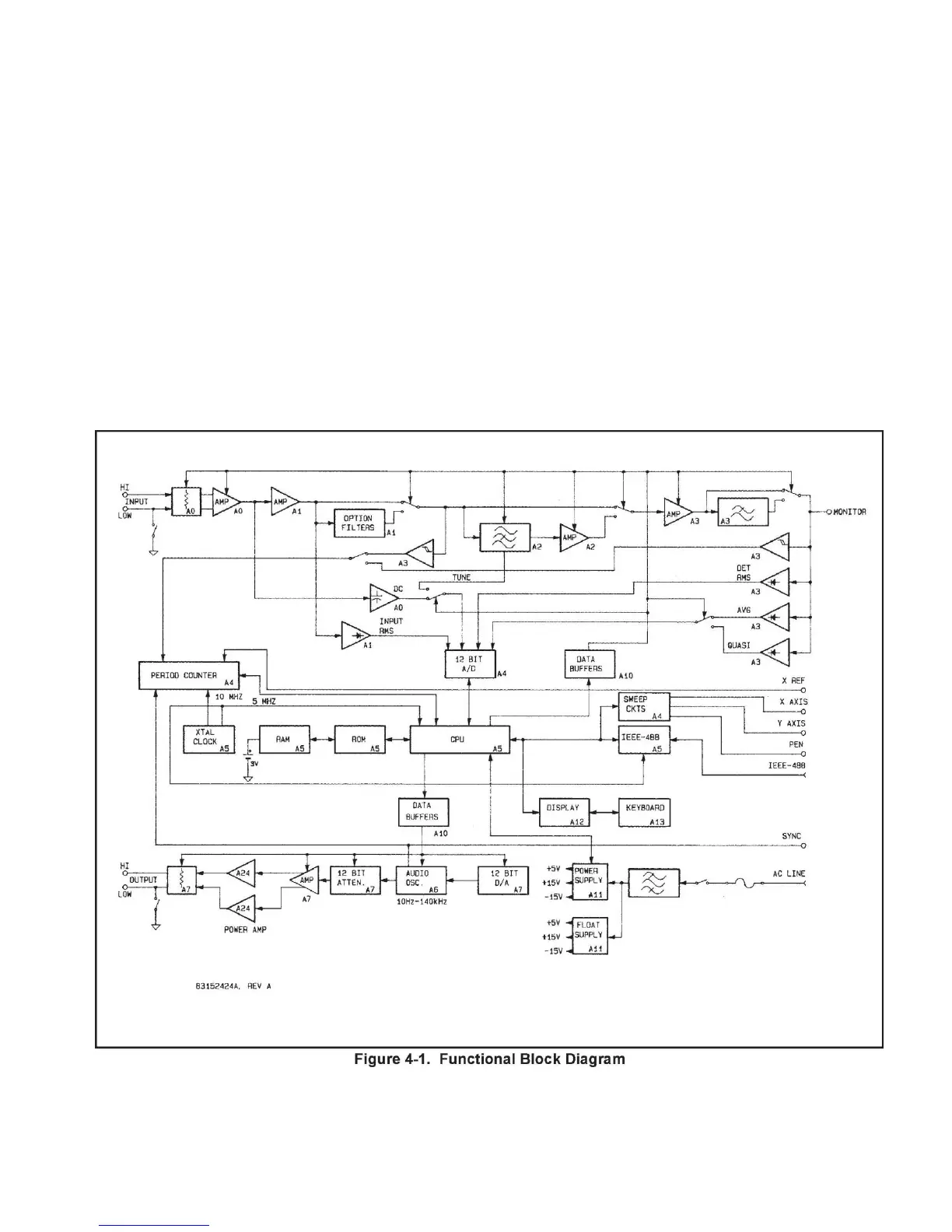
4-3. FUNCTIONAL BLOCK DIAGRAM.
4-4. Control of the instrument operation is exercised
by a microprocessor that executes a fixed program


 To Next Page